Vacuum Circuit Breaker MVS13-12 (ZN28)

  • Share:

Description


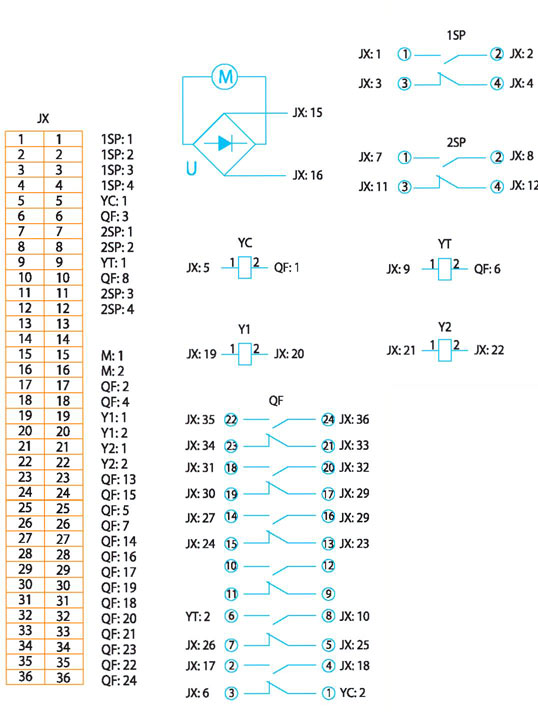
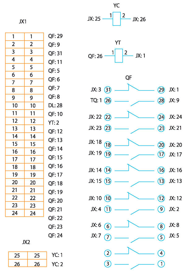
MVS13-12 (ZN28) — indoor vacuum circuit breaker for alternating current networks, manufactured by METTZ Group.

The MVS13-12 series vacuum circuit breaker is designed for switching electrical circuits under normal and emergency conditions in three-phase alternating current networks with a voltage of 10 kV and a frequency of 50 Hz.

MVS13-12 is usually installed in switchgear cubicles. The circuit breaker complies with the requirements of IEC IEC60056.

Parameters


Main characteristics and operating conditions:

 — Temperature: -15 ° C ~ + 45 ° C;

— Installation height above sea level: no more than 1000 m;

— Relative humidity:

daily average: not more than 95%;

monthly average: not more than 90%;

— Saturated vapor pressure:

daily average: not more than 2.2 kPa;

monthly average: not more than 1.8 kPa;

— earthquakes: no more than 8 points;

— Condition: operation in fireproof, explosion proof places, absence of pollution and strong vibration.


Technical specifications:

No. Parameter Unit. Value

  1. Rated voltage kV 12
  2. Rated current A 630,1000,1250,1600, 2000,2500,3150
  3. Rated short-circuit breaking current kA 20,25,31.5,40
  4. Rated short circuit current (peak) kA 50, 63.80,100
  5. Peak withstand current kA 50, 63.80,100
  6. Short-time withstand current kA 20,25,31.5,40
  7. Rated short circuit duration with 4
  8. Shutdown of short circuit current Quantity 50

VZN28-12 / D

  1. Nominal cycle of operations kV 0-0.3s-c0-180s-c0
  2. Withstand voltage of industrial frequency, 1 min kV 42
  3. Lightning impulse withstand voltage 75
  4. Mechanical wear resistance Quantity 10000
  5. Rated operating voltage V -110 / ~ 110, -220 / ~ 220
  6. The distance between the centers of the poles mm 210 ± 2.5 (1600A and below), 230 ± 2.5 (1600A and below), 250 ± 2.5 (2000,2500 A) 275 ± 2.5 (3150 A)

Solutions


MVS13-12-2

Appearance of the switch of the MVS13-12 series

Note: the drive mechanism is in a dotted frame;

No. 17 (insulating partition) is not necessary; the distance between centers is 230 mm or 250 mm (if the distance between centers is 210 mm, see size in brackets).

VZN28-12 / DD-D

5.2 Installation dimensions of the circuit breaker of the VZN28-12 series (see Fig. 5.2, 5.3, 5.4.5.5)

MVS13-12-1

Mounting Dimensions for MVS13-12 series

Note: the drive mechanism is dotted. If

65

A = 210 mm, B = 551 mm, C = 695 mm, 0 = 560 mm, E = 590 mm A = 230 mm, B = 586 mm, C = 715 mm, 0 = 600 mm, E = 630 mm A = 250 mm, B = 626 mm, C = 715 mm, D = 640 mm, E = 670 mm A = 275 mm, B = 700 mm, C = 780 mm, D = 700 mm, E = 730 mm

Sizes and position of exits
image005

Mounting Dimensions for VZN28-12 Series Switch

Note: if A = 210 mm, 0 = 560 A = 230 mm, 0 = 600 A = 250 mm, 0 = 640 A = 275 mm, 0 = 700

the distance between the phases A = 210 mm, A = 230 mm, A = 250 mm

image006

SP 9 spring drive

Solenoid Drive CD17

Dimensions and location of holes on the front panel

Pole spacing A B C D E

210 364 64 25 56 258

230 384 44 45 56 278

250 384 44 45 56 278

275 450 19 70 26 344

Note: if the distance between phases is 210 mm (see size in brackets).

VZN28-12 / DD-D

Schematic diagram of the spring drive CE19

Schematic diagram of the CT19 spring drive (the drive is in the off position, the spring is not cocked)

K: switch

ZJ: Auxiliary Relay

KK: Key management

SP: Travel Switch

M: Engine

YC: Inclusion coil

YT: Trip coil

image007

Inner contour

Control circuit
image008

JX: Terminal Block YC: Inclusion Coil

YT: Shutdown coil

M: Engine

SP: Travel Switch

QF: Auxiliary switch

Y1, Y2: Current coil

U: Rectifier (using alternating current)

QF: Auxiliary switch


Schematic diagram of the electromagnetic drive CD17:

image009

JX: Terminal block YC: Closing coil YT: Circuit breaking QF: Auxiliary switch

When ordering, please indicate:

Type, name, main technical parameters and number of switches;

Type and voltage of the drive; if the spring drive should indicate the number of current coils;

Name and quantity of spare parts and accessories;

If the switch requires mechanical interlock, please indicate the location of the main shaft and its length.