
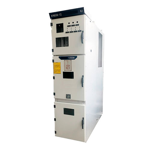
Metal-clad switchgear is the workhorse of medium-voltage distribution in plants, utilities and data centres. Its real value is not the steel but the way it forces safe operation: every live part is behind an earthed barrier, every movement is interlocked, and an internal fault is steered away from people. This article walks through a typical panel, compartment by compartment, and explains the safety logic behind each feature.
Where Metal-Clad Switchgear Fits
In most networks it sits between the source (a utility incomer, transformer secondary or generator) and the loads, typically at 3.6 kV to 40.5 kV. Each vertical section, or functional unit, contains a withdrawable circuit breaker plus its protection, metering and cable termination. In IEC terms such a panel is usually classified LSC2B with metallic partitions (PM); in ANSI markets the equivalent construction is defined by IEEE C37.20.2. The difference between the two vocabularies is covered in our separate comparison of metal-clad and metal-enclosed switchgear, so here the focus is on how the equipment works.
Anatomy of a Panel
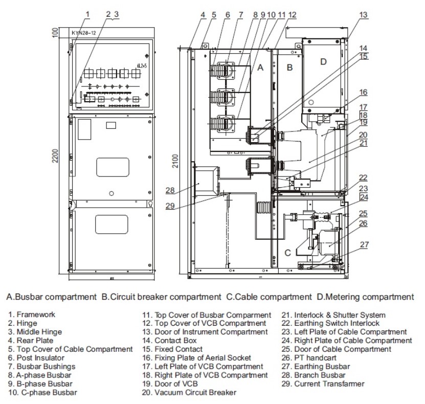
A typical metal-clad functional unit is split into four or five compartments, each separated by earthed sheet steel.
| Compartment | What it contains | Safety purpose |
|---|---|---|
| Circuit breaker compartment | Withdrawable breaker truck, primary contact spouts, shutters | Lets the breaker be removed without exposing live parts |
| Busbar compartment | Main busbars running through the line-up | Keeps the bus away from work on any single feeder |
| Cable compartment | Cable terminations, current transformers, earthing switch, surge arresters, sometimes VTs | Allows cable work while the bus stays live |
| Low-voltage compartment | Protection relay, meters, control wiring, auxiliary supplies | Lets operators work on secondary circuits with no MV exposure |
| Pressure relief duct (above panel) | Flaps and channel to vent arc gases | Directs hot gas away from accessible sides |
How the Withdrawable Breaker Works
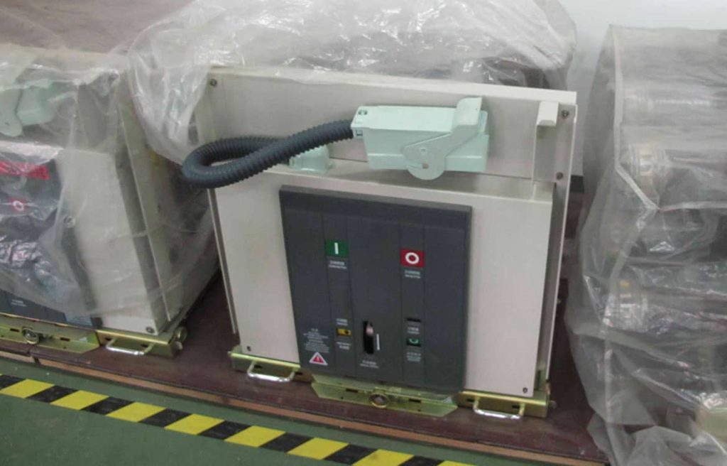
The circuit breaker, today almost always a vacuum breaker, rides on a truck or cassette. It moves between three defined positions:
- Service (connected): primary and secondary contacts engaged; the breaker can carry and switch load current and clear faults.
- Test: primary contacts separated by a safe isolating distance, secondary plug still connected. Operators can close and trip the breaker to check control and protection without energizing the feeder.
- Withdrawn (disconnected): both primary and secondary disconnected; the truck can be rolled out onto a service trolley.
Because the isolating gap is created by physically moving the breaker, the panel does not need a separate disconnector. The breaker itself detects nothing: a protection relay measures current through the CTs (and voltage through VTs where needed) and sends a trip signal when it sees overcurrent, earth fault or another abnormal condition. The vacuum interrupters then break the current at the next current zero.
Shutters
When the truck leaves the service position, spring-loaded metal shutters close automatically over the fixed contact spouts. They can be padlocked closed, so nobody can push a finger or tool towards the live busbar or cable side.
Interlocks: Forcing the Right Sequence
Most switching accidents happen when someone does the right thing in the wrong order. Metal-clad panels use mechanical interlocks, often backed by electrical ones, to make wrong sequences impossible. Typical rules are:
- The breaker cannot be racked in or out while it is closed.
- The breaker can only be closed when it is fully in the service or test position, never in between.
- The earthing switch can only be closed when the breaker truck is in the test or withdrawn position.
- The truck cannot be racked to service while the earthing switch is closed.
- The cable compartment door can only be opened when the earthing switch is closed.
- Key interlocks can link panels, for example to stop two incomers and a bus coupler from paralleling unintentionally.
Earthing and Proof of Dead
Before anyone touches a cable, it must be proved dead and earthed. Metal-clad panels support this with:
- An earthing switch in the cable compartment. A switch with short-circuit making capability (class E1 or E2 to IEC 62271-102) protects the operator even if the cable turns out to be live when the switch is closed.
- Voltage presence indicating systems (to IEC 62271-213) on the front, fed by capacitive sensors, so operators can check voltage without opening anything.
- Earthing trucks or test plugs for earthing busbars during bus maintenance.
Containing an Internal Arc
An internal arc, for example from failed insulation, a loose joint or an animal, releases enormous energy in milliseconds. Pressure rises sharply, metal vaporizes and hot gas looks for a way out. Metal-clad design deals with it in layers.
Passive protection
- Type-tested enclosure: an IAC rating to IEC 62271-200 (for example IAC AFLR 31.5 kA 1 s) proves that doors stay closed, no parts fly off and no hot gas escapes towards the tested sides.
- Pressure relief flaps and ducts carry gases upward and out of the room, or into an absorber, instead of through the front doors.
- Compartment partitions limit the arc to one compartment, so damage stays local.
Active protection
- Arc flash detection relays combine light sensors with a fast overcurrent check. They issue a trip command within a few milliseconds, so total clearing time is set mainly by the breaker, typically 50-80 ms instead of hundreds of milliseconds from graded overcurrent protection.
- Active arc quenching devices create a deliberate, controlled short circuit in a few milliseconds, which collapses the arc before the upstream breaker opens.
- Bus differential or zone-selective interlocking lets the incomer trip fast for a bus fault while staying selective for feeder faults.
Keeping People Out of the Arc Zone
The safest operator is one who is not standing in front of the panel. Modern line-ups support:
- Racking with the door closed through a front aperture, and motorized remote racking from outside the arc boundary.
- Remote open/close from a control room or SCADA.
- Online condition monitoring: wireless temperature sensors on cable lugs and contacts, partial discharge sensors, and breaker operation counters. These reduce the number of intrusive inspections in the first place.
Where It Is Used
- Utility primary and secondary substations, especially incomers and bus couplers.
- Process plants, mines, cement and steel works with large motor feeders.
- Data centres and hospitals, where a failed breaker must be swapped without a bus outage.
- Generation and renewable plants, including solar and wind collection systems and battery storage connections.
Frequently Asked Questions
Does metal-clad switchgear eliminate arc flash risk?
No. It reduces the likelihood of a fault and channels the energy away from accessible sides if the panel has an IAC rating. Safe procedures, correct PPE and fast protection are still needed.
Why is the test position useful?
It lets operators check closing, tripping and relay logic with the primary circuit isolated, which is essential after maintenance or protection setting changes.
Can a breaker be racked out while carrying current?
No. The interlock prevents racking unless the breaker is open, because pulling the primary contacts under load would draw an arc.
Are vacuum breakers standard in metal-clad switchgear today?
Yes, at distribution voltages vacuum is the dominant technology. It needs little maintenance and avoids SF6 in the interrupter.
Work with METTZ Group
METTZ Group offers a wide range of air-insulated medium-voltage switchgear to suit many needs, from single feeder panels to complete line-ups with withdrawable indoor vacuum circuit breakers, earthing switches and instrument transformers. Check out our website to learn more, or contact METTZ Group today to work with a representative.
