
A 32 A circuit breaker protects some of the hardest-working circuits in a building: EV chargers, cookers, water heaters, air conditioners and small motors. Picking the right one takes more than reading the current rating. This guide covers the choice between MCB and MCCB, tripping curves, breaking capacity, poles, residual current protection and cable sizing.
Where 32 A breakers are used
At 230 V single-phase, 32 A corresponds to about 7.4 kW; at 400 V three-phase, to about 22 kW. Typical circuits include:
- Single-phase EV chargers rated 7.4 kW and three-phase chargers rated 22 kW.
- Electric cookers, ovens and hobs.
- Instantaneous water heaters and heat pumps.
- Air conditioning and ventilation units.
- Ring final circuits in UK-style installations.
- Workshop machines, small pumps and compressors.
- Sub-main feeds to small distribution boards.
In North American practice, 32 A is not a standard breaker rating; 30 A and 40 A are used instead. This guide follows IEC practice.
Step 1: MCB or MCCB?
| Feature | MCB (miniature circuit breaker) | MCCB (molded case circuit breaker) |
|---|---|---|
| Standard | IEC 60898-1 (household and similar); IEC 60947-2 for industrial versions | IEC 60947-2 |
| Typical rating range | Up to 63 A, some to 125 A | From about 16 A up to 1,600 A and more |
| Trip settings | Fixed (curve B, C or D) | Fixed or adjustable; thermal-magnetic or electronic |
| Breaking capacity | Typically 6 kA or 10 kA (Icn), up to 25 kA for industrial types | Typically 25 kA to 100 kA or more (Icu) |
| Mounting | DIN rail in distribution boards | Panel or plate mounting in switchboards and LV cabinets |
| Best fit at 32 A | Final circuits in homes, offices, shops, light industry | Feeders close to a large transformer, or where adjustable settings and high breaking capacity are needed |
For most 32 A final circuits, an MCB is the right choice. An MCCB becomes necessary when the prospective short-circuit current at the board exceeds the MCB’s rating, or when selectivity with upstream devices requires adjustable trip settings.
Step 2: Choose the tripping curve
Every thermal-magnetic breaker has two trip elements. The thermal element responds to sustained overloads; the magnetic element trips instantly on high currents. The curve letter sets where the instantaneous trip begins, as a multiple of the rated current In:
| Curve | Instantaneous trip range | For a 32 A breaker | Typical loads |
|---|---|---|---|
| B | 3-5 × In | 96-160 A | Resistive loads, long cables, domestic circuits |
| C | 5-10 × In | 160-320 A | General commercial use, small motors, LED drivers, air conditioners |
| D | 10-20 × In | 320-640 A | High inrush: transformers, large motors, welding sets |
Use the lowest curve that does not trip on normal inrush. A lower curve trips faster on faults and makes it easier to meet the disconnection times required by IEC 60364-4-41 on long circuits. A D curve on a long cable may not trip quickly enough during an earth fault, so the loop impedance must be checked.
Step 3: Check the breaking capacity
The breaking capacity is the highest short-circuit current the breaker can safely interrupt. It must be at least equal to the prospective short-circuit current at the point of installation.
- Under IEC 60898-1, the rated short-circuit capacity is Icn, commonly 4.5, 6 or 10 kA.
- Under IEC 60947-2, two values are given: Icu (ultimate) and Ics (service, at which the breaker remains fit for use).
A typical home far from the transformer may see only 1-3 kA, but a board in a commercial building close to a 1,000 kVA transformer can see 20 kA or more. When the fault level exceeds the breaker’s own rating, cascading (backup protection) by a tested upstream device may be allowed, but only using combinations confirmed by the manufacturer.
Step 4: Select the number of poles and voltage
- 1P: single-phase circuits where the neutral does not need to be switched.
- 1P+N or 2P: single-phase circuits where the neutral must be isolated, for example in TT systems or for EV chargers.
- 3P: three-phase loads without neutral, such as motors.
- 4P: three-phase circuits with neutral, or where all live conductors must be isolated.
Confirm the rated operational voltage (for example 230/400 V AC). For DC circuits, such as solar PV strings or battery systems, use breakers rated and marked for DC; AC breakers are not suitable.
Step 5: Size the cable to the breaker
The breaker protects the cable, not the appliance. Under IEC 60364-4-43, the rated current In must not exceed the cable’s current-carrying capacity Iz under its actual installation conditions. For MCBs to IEC 60898-1, this simple rule is enough, because their conventional tripping current is 1.45 × In.
For copper PVC-insulated cable with two loaded conductors, IEC 60364-5-52 gives approximate capacities of:
- 4 mm²: about 37 A clipped direct (method C), 32 A in conduit on a wall (method B1), 26 A in conduit in an insulated wall (method A1).
- 6 mm²: about 47 A (method C), 41 A (method B1), 34 A (method A1).
So 4 mm² can work for a 32 A circuit only in favorable conditions. Once you apply correction factors for higher ambient temperature, grouping with other circuits or thermal insulation, 6 mm² is the common choice, and 10 mm² may be needed for long runs. Also check:
- Voltage drop: often limited to 3-5% for final circuits; a 32 A load over 30 m or more may need a larger cable.
- Earth fault loop impedance: it must be low enough for the breaker to disconnect within the required time.
- Terminal capacity: the breaker’s terminals must accept the chosen cable size.
Local wiring rules, such as BS 7671 in the UK or national IEC-based codes, may impose further limits. When in doubt, ask a qualified designer to do the calculation.
Step 6: Add residual current protection where required
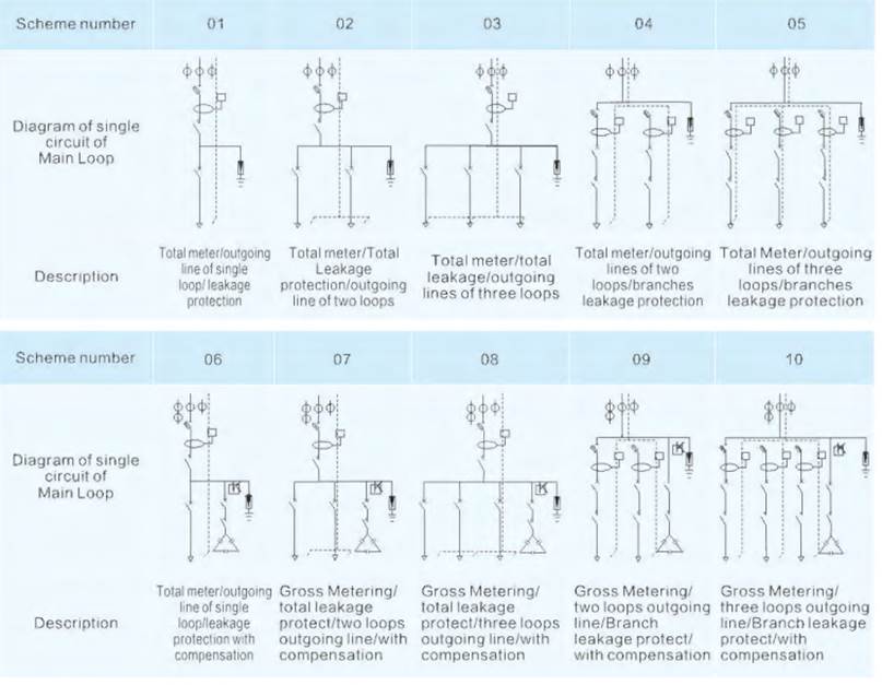
An MCB does not protect people against electric shock from small earth leakage currents. Many circuits need a residual current device (RCD) or a combined RCBO:
- 30 mA RCD for socket outlets and many final circuits, as required by IEC 60364-4-41 and most national codes.
- EV chargers need a dedicated circuit with a 30 mA RCD, Type A combined with 6 mA DC fault detection in the charger, or Type B, according to IEC 60364-7-722.
- Type F or Type B RCDs for equipment with variable-speed drives, such as heat pumps and inverter air conditioners, if the manufacturer requires it.
Step 7: Consider installation conditions
- MCBs are calibrated at a reference temperature, usually 30 °C. In hot enclosures or tropical climates, the thermal trip occurs at a lower current; apply the manufacturer’s derating factors.
- Many MCBs side by side in a crowded board run warmer than one alone. IEC 61439-3 boards define a rated diversity factor that accounts for this.
- For continuous loads such as EV chargers and heaters, leave margin: running a 32 A breaker permanently at 32 A in a warm board can lead to nuisance tripping.
- Check selectivity with the upstream device so that a fault on the 32 A circuit does not trip the main supply.
Quick checklist
- Load current confirmed and 32 A appropriate.
- MCB (IEC 60898-1) or MCCB (IEC 60947-2) chosen.
- Curve B, C or D chosen for the inrush and cable length.
- Breaking capacity at least equal to the prospective fault current.
- Poles and voltage rating (AC or DC) correct.
- Cable sized for In ≤ Iz with all correction factors, voltage drop and loop impedance checked.
- RCD or RCBO added where required.
- Installation by a qualified electrician, with tests and documentation.
Frequently Asked Questions
What cable size is needed for a 32 A breaker?
Usually 6 mm² copper. A 4 mm² cable can be used only where the installation method and correction factors give a capacity of at least 32 A, and voltage drop allows it.
Can I replace a 20 A breaker with a 32 A one?
Only if the cable is rated for 32 A under its installation conditions. Upsizing the breaker on an undersized cable creates a fire risk.
Should I use a B or C curve for an EV charger?
Both are used. Follow the charger manufacturer’s instructions; many specify a C curve, combined with the required residual current protection.
Why does my 32 A breaker trip under normal load?
Common causes are a load close to or above 32 A for long periods, high temperatures in the board, inrush current that exceeds the curve, loose connections or an actual fault. Have the circuit checked by an electrician.
Work with METTZ Group
METTZ Group offers a wide range of distribution boards to suit many needs – from compact final-distribution boards for residential and commercial buildings to low-voltage cabinets for industrial plants and infrastructure, with matching LV components. Check out our website to learn more, or contact METTZ Group today to work with a representative.
