
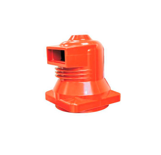
Inside every medium-voltage panel, a set of cast epoxy parts holds live conductors in place, separates compartments and carries the plug-in contacts of the circuit breaker. These insulation accessories rarely appear on a single-line diagram, yet they decide how well the panel resists flashover, partial discharge and moisture. This article explains each part, how to select it and what failure looks like.
What Are Switchgear Insulation Accessories?
The term covers the solid insulating parts that support, guide or enclose energized conductors inside switchgear. In modern MV panels almost all of them are cast from epoxy resin filled with silica or alumina, using automatic pressure gelation (APG) or vacuum casting. The result is a dense, void-free part with high dielectric strength, good mechanical strength and stable dimensions.
They have three jobs:
- Electrical: withstand the rated power-frequency and lightning impulse voltages without breakdown or harmful partial discharge.
- Mechanical: hold conductors in place during the electromagnetic forces of a short circuit and the repeated insertion of breaker contacts.
- Segregation: form part of the barriers between busbar, breaker and cable compartments.
General-purpose insulator types and materials, such as porcelain, glass and composite line insulators, are covered in our separate article on electrical insulators. Here the focus is on the specific parts used inside switchgear panels.
Contact Boxes (Spouts)
A contact box, also called a spout or contact housing, is the cup-shaped epoxy part mounted in the partition at the back of the breaker compartment. It carries the fixed contact that the breaker’s tulip (cluster) contact engages when the truck is racked into the service position. Each withdrawable panel normally has six: three upper (busbar side) and three lower (cable side).
How a contact box works
The fixed contact, usually a silver-plated copper bar or stud, is cast or bolted into the epoxy body. Its rear end connects to the busbar or cable bar; its front end sits inside the cup. The cup’s depth and ribbed outer surface give the creepage distance needed between the live contact and the earthed partition. When the truck racks out, metal shutters close in front of all six spouts.
Selection points
- Rated voltage: 12, 24 or 40.5 kV, with matching insulation level.
- Rated current: typically 630, 1,250, 1,600, 2,500, 3,150 or 4,000 A. Higher ratings use larger diameters, more contact fingers and sometimes forced ventilation.
- Short-time current: the fixed contact and its fixings must withstand the panel’s rated short-time and peak currents.
- Geometry: mounting flange, contact diameter and phase spacing must match the breaker truck and panel. Contact boxes are not interchangeable between designs without checking dimensions.
- Partial discharge level: ask for routine PD test results to IEC 60270.
- Integrated features: some contact boxes include a capacitive tap for voltage indication or mounting points for temperature sensors.
Post Insulators and Busbar Supports
Epoxy post insulators hold busbars and cable bars at the correct distance from the enclosure and from each other. Indoor organic post insulators are covered by IEC 60660. When choosing them, check rated voltage, cantilever (bending) strength, which must cover the forces during peak short-circuit current, creepage distance and the thread size of the inserts at each end.
Insulators with sheds (ribs) add creepage distance without extra height, which matters in humid or polluted switch rooms.
Sensor Insulators and Capacitive Dividers
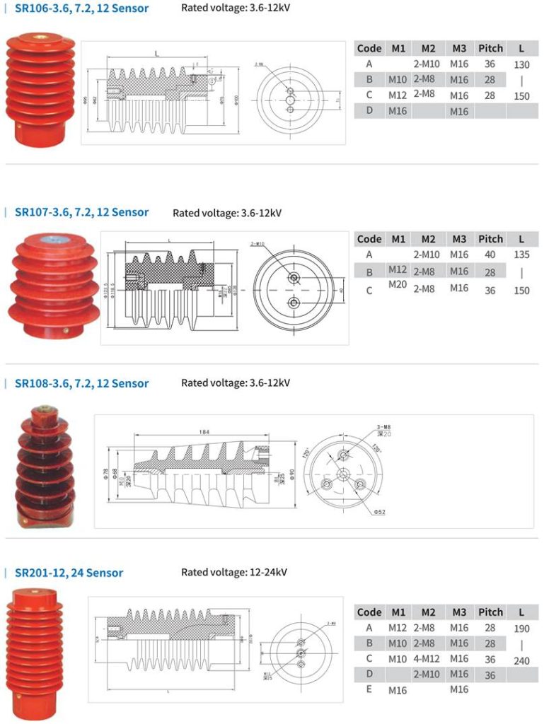
A sensor insulator looks like a standard post insulator but contains a cast-in electrode that forms a capacitive divider. The low-voltage tap feeds:
- Voltage presence indicating systems (VPIS) to IEC 62271-213, showing operators whether a circuit is live before earthing.
- Voltage detecting systems (VDS) to IEC 61243-5 for portable testers.
- Low-power voltage transformers to IEC 61869-11, which give a measurement signal for digital protection relays and power quality meters.
Combined sensors that hold both a low-power current sensor and a capacitive voltage divider in one epoxy body are increasingly used in compact and digital switchgear, replacing heavier conventional CTs and VTs.
Insulating Barriers, Sleeves and Covers
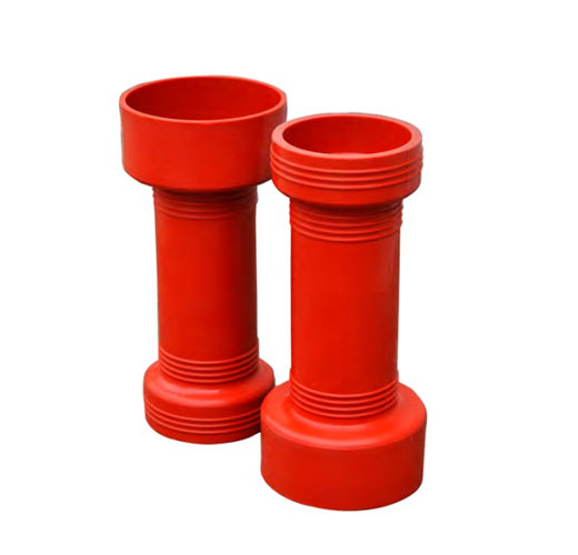
- Interphase barriers: sheets of SMC, DMC or other insulating material between phases where clearances are tight.
- Busbar sleeves: heat-shrink tubing that reduces the risk of flashover from foreign objects and animals.
- Joint covers: molded boots over bolted joints.
- Insulating partitions (class PI): in some designs these replace metal partitions between compartments.
Note that sleeves and covers improve reliability but do not make a bare conductor touch-safe. Clearances must still meet the type-tested design.
Wall Bushings and Cable Bushings
Wall bushings pass busbars through partitions between panels or compartments, while cable bushings to EN 50181 provide plug-in interfaces for T-connectors in compact switchgear and RMUs. Wall bushings are covered in detail in our dedicated bushing guide.
Selection Checklist
| Parameter | What to check |
|---|---|
| Rated voltage and insulation level | Equal to or higher than the panel rating; e.g. 12 kV with 42/75 kV where national grids require higher power-frequency values |
| Rated and short-time current | Matches the circuit it carries, including peak withstand |
| Creepage distance | Suitable for the room’s pollution and condensation class (IEC TS 62271-304) |
| Material | Epoxy grade, filler and thermal class; resistance to tracking (CTI) for sheet barriers |
| Partial discharge | Routine PD test with a stated maximum level at the test voltage |
| Mechanical data | Bending strength, insert threads, tightening torque |
| Dimensions and interfaces | Drawing check against the breaker truck and panel |
Common Problems and Early Warning Signs
- Surface tracking: dark, branching marks on epoxy, caused by dust plus condensation. Clean, dry and improve heating or ventilation; replace badly tracked parts.
- Partial discharge: ozone smell, hissing, white powder near edges. Confirm with TEV or ultrasonic sensors.
- Overheating of contact boxes: discolored silver plating or epoxy near the fixed contact, often from worn tulip contacts or insufficient insertion depth. Thermal imaging and wireless temperature sensors catch this early.
- Cracks: from overtightened bolts, mechanical impact or thermal cycling. A cracked epoxy part must be replaced, never repaired with filler.
Maintenance Tips
- Inspect visually during every planned outage; clean with dry, lint-free cloth or approved cleaning agents.
- Check insertion depth and contact pressure of the breaker’s tulip contacts in each contact box.
- Measure insulation resistance and, where possible, perform PD measurements to track trends.
- Keep anti-condensation heaters working and the switch room sealed against dust and animals.
Frequently Asked Questions
What is the difference between a contact box and a bushing?
A contact box houses the fixed contact for a withdrawable breaker and forms a cup the moving contact enters. A bushing simply carries a conductor through a wall or partition.
Can contact boxes from one panel design fit another?
Only if dimensions, current rating, contact diameter and phase spacing match. Always compare drawings and confirm that the assembly remains within its type-tested design.
How long do epoxy insulation parts last?
Properly made and installed parts usually last the full life of the switchgear, often 30 years or more, provided the room is kept dry and clean.
Work with METTZ Group
METTZ Group offers a wide range of switchgear components to suit many needs – from contact boxes and epoxy insulators to vacuum interrupters and embedded poles for air-insulated switchgear. Check out our website to learn more, or contact METTZ Group today to work with a representative.
