
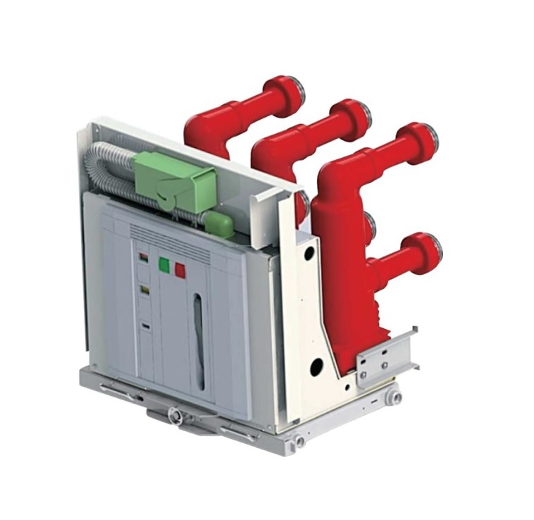
A medium-voltage circuit breaker is the device that clears faults in feeders, transformers and motors between 1 kV and roughly 36-52 kV. This guide explains what the breaker actually does, which technologies are in use today and how to read the IEC 62271-100 ratings that decide whether a breaker fits your network.
What a Medium-Voltage Circuit Breaker Does
A circuit breaker is a mechanical switching device that can make, carry and break currents under normal conditions, and make, carry for a specified time and break currents under abnormal conditions such as a short circuit. That last ability separates it from a load break switch or a disconnector.
IEC defines medium voltage as above 1 kV AC. In practice, “MV” covers rated voltages of 3.6, 7.2, 12, 17.5, 24 and 36 kV (40.5 kV in some markets), with 52 kV as the usual upper boundary. The 10-35 kV band you often see quoted is simply the most common range, not the definition.
Breakers trip on current, not on a voltage threshold
An MV breaker has no built-in “voltage threshold”. It opens when it receives a trip command. That command comes from a protection relay, which measures current through current transformers (CTs) and, where needed, voltage through voltage transformers (VTs). Typical functions include:
- Overcurrent and short-circuit protection (ANSI 50/51)
- Earth-fault protection (50N/51N)
- Directional, differential or under/over-voltage protection on more complex networks
- Auto-reclosing on overhead lines, where most faults are temporary
The relay decides when to trip; the breaker’s job is to interrupt the fault current safely within its rated capability. Many compact breakers now ship with self-powered relays that draw their energy from the CTs, so no auxiliary battery is needed for protection.
Operating Mechanisms: How the Contacts Move
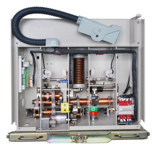
Every MV breaker needs stored energy to open and close its contacts quickly and independently of the operator’s speed. Three mechanism types dominate:
- Spring-stored energy mechanism. A motor (or a hand crank) charges a closing spring; closing then charges the opening spring. All spring breakers can be operated manually on site with push buttons and a charging handle, at any rated voltage. Manual operation is therefore available on MV breakers too, not only on low-voltage devices.
- Permanent-magnet actuator. A single moving armature latched by permanent magnets, driven by capacitor discharge. It has very few parts and suits high operation counts.
- Solenoid mechanism. Found on older designs; largely replaced by the two above.
Shunt trip coils, undervoltage releases, closing coils, auxiliary contacts and operation counters complete the mechanism and let the breaker be controlled remotely from SCADA.
Main Types of MV Circuit Breakers
Breakers are named after the medium that extinguishes the arc between the opening contacts:
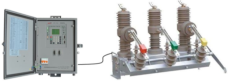
- Vacuum circuit breakers (VCB) – the dominant technology from 3.6 to 40.5 kV. The arc burns in a sealed vacuum interrupter and is quenched at the first current zero. Compact, low-maintenance and free of greenhouse gases.
- SF6 circuit breakers – use sulfur hexafluoride gas; strong at higher voltages, but SF6 is a potent greenhouse gas now being phased out of new MV equipment in several regions.
- Air-magnetic breakers – legacy MV designs using arc chutes; at low voltage, air circuit breakers (ACBs) remain standard up to 1 kV.
- Bulk-oil and minimum-oil breakers – still in service on older networks but no longer specified for new projects because of fire risk and maintenance.
For a detailed side-by-side comparison, see our article on vacuum, SF6, air and oil breakers. For most new indoor and outdoor MV projects, the practical choice is a vacuum circuit breaker, with SF6 circuit breakers kept for specific retrofit or high-voltage cases.
How to Select an MV Circuit Breaker by Its Ratings
IEC 62271-100 defines the ratings that must be matched to the network. The table below lists the key values and what to check against them.
| Rating | Typical values | What to check |
|---|---|---|
| Rated voltage (Ur) | 7.2, 12, 17.5, 24, 36, 40.5 kV | Equal to or above the highest system voltage |
| Rated insulation level | e.g. 12 kV: 28 kV power-frequency / 75 kV lightning impulse; 24 kV: 50 / 125 kV | Altitude above 1,000 m and pollution may need a higher level |
| Rated normal current (Ir) | 630, 1,250, 1,600, 2,000, 2,500, 3,150, 4,000 A | Maximum continuous load plus growth margin, derated for ambient temperature |
| Rated short-circuit breaking current (Isc) | 16, 20, 25, 31.5, 40, 50 kA | Must exceed the prospective fault level at the installation point |
| Rated short-circuit making current | 2.5 × Isc (50 Hz) or 2.6 × Isc (60 Hz) peak | Closing onto a fault without welding contacts |
| Rated short-time withstand current and duration | Equal to Isc for 3 s (or 1 s) | Coordination with downstream protection time |
| Rated operating sequence | O-0.3 s-CO-3 min-CO or O-3 min-CO-3 min-CO | Fast auto-reclosing on overhead lines |
| Mechanical / electrical endurance | Class M1/M2, E1/E2 | M2 (10,000 operations) for frequent switching |
| Capacitive switching class | C1 / C2 | C2 for capacitor banks and long cables |
Practical selection steps
- Confirm the system voltage and earthing. Pick the next standard Ur above the highest operating voltage.
- Calculate the fault level. Use the upstream transformer impedance and network data; include motor contribution and future reinforcement.
- Define the load duty. Feeders, transformers, motors and capacitor banks impose different switching duties. Motors and dry-type transformers may need surge protection against switching overvoltages.
- Choose the installation type. Indoor withdrawable or fixed breakers for metal-enclosed switchgear; outdoor pole-mounted or post-type breakers for overhead lines; ruggedized versions for mining.
- Match the control voltage and interfaces. Coil voltages, motor voltage, auxiliary contacts and communication with the substation automation system.
- Check environment. Ambient temperature, humidity, altitude, dust and tropical conditions all affect ratings and enclosure choice.
Where MV Circuit Breakers Are Used
MV breakers protect incoming and outgoing feeders in:
- Utility distribution substations and pole-mounted reclosers on overhead lines
- Industrial plants, mines, cement, steel and petrochemical sites
- Data centres, hospitals, airports and commercial buildings with their own MV intake
- Solar and wind farms, battery energy storage systems and EV charging hubs
- Generator, motor and transformer feeders in power stations
In each case the breaker usually sits inside medium-voltage switchgear designed and type-tested to IEC 62271-200, together with CTs, VTs, relays, earthing switches and interlocks.
Frequently Asked Questions
What voltage range counts as medium voltage?
Under IEC practice, MV starts above 1 kV AC and usually ends at 36 kV or 52 kV. Standard breaker ratings include 12, 24 and 36 kV, with 40.5 kV used in some regions.
Does an MV circuit breaker detect faults by itself?
No. A protection relay measures current and voltage through instrument transformers and sends a trip command. The breaker then interrupts the current within its rated breaking capacity.
Can an MV breaker be operated manually?
Yes. Spring-operated MV breakers have manual charging, close and open controls on the front panel, and can also be operated remotely through coils and a charging motor.
Which breaker type is best for new projects?
For most applications up to 40.5 kV, vacuum circuit breakers offer the best balance of compact size, low maintenance and environmental performance.
Work with METTZ Group
METTZ Group offers a wide range of medium-voltage circuit breakers to suit many needs – from indoor withdrawable VCBs for switchgear panels to outdoor pole-mounted breakers and mining versions, with equipment available from 1 kV up to 220 kV. Check out our website to learn more, or contact METTZ Group today to work with a representative.
