
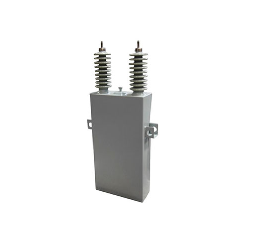
Shunt capacitor banks are one of the cheapest and most effective tools for improving distribution networks. This article explains how they work, what they deliver, how to size and place them, and how to avoid the harmonic problems that modern loads can cause.
Why Networks Need Reactive Power
Motors, transformers, induction furnaces and many other loads need a magnetic field to work. Building that field takes reactive power (kvar), which flows back and forth without doing useful work. With inductive loads, current lags behind voltage, and power factor (PF = kW / kVA) drops below 1.
If the utility’s generators supply all that reactive power, it has to travel through every line and transformer in between. This brings three problems:
- Higher current for the same useful power, so I²R losses rise (a PF of 0.8 means about 56% more loss than at unity PF).
- Larger voltage drop along feeders, with low voltage at the far end.
- Wasted capacity in transformers, cables and generators, which are rated in kVA, not kW.
How a Shunt Capacitor Helps
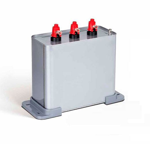
A capacitor connected in parallel (shunt) with the load draws a leading current that cancels part of the lagging inductive current. In effect, it supplies reactive power locally, so the network upstream only has to carry the active power plus whatever reactive power remains. The benefits:
- Improved power factor, and lower or no reactive-power charges on the electricity bill.
- Lower current, which means lower losses in feeders and transformers.
- Better voltage profile along the feeder.
- Released capacity. An existing transformer or line can serve more kW without an upgrade.
Voltage rise from a shunt capacitor is roughly ΔV ≈ QC · X / V². At a substation bus, the rise as a percentage is approximately equal to the bank rating divided by the short-circuit power. That makes it easy to check that switching a bank will not push voltage above limits.
Sizing a Capacitor Bank
The required reactive power follows from the active power P and the power factors before and after correction:
QC = P × (tan φ1 – tan φ2)
Example: a 500 kW plant at PF 0.75 that must reach PF 0.95 needs QC = 500 × (0.882 – 0.329) ≈ 277 kvar. In practice, you would choose a 300 kvar automatic bank in several steps so the output can follow the load.
Avoid over-correction. A leading power factor at light load can raise voltage and may also be penalized.
Where Shunt Capacitors Are Installed
| Location | Typical voltage and size | Main purpose |
|---|---|---|
| At individual motors (LV) | 0.4-0.69 kV, a few to tens of kvar | Fixed compensation of large, continuously running motors |
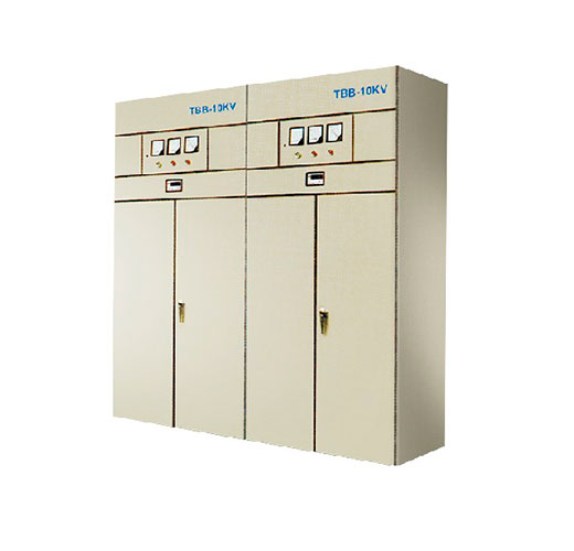
| LV main switchboard | 0.4-0.69 kV, 50-1,000+ kvar, automatic steps | Plant-wide PF correction and tariff savings |
| Pole-mounted on MV feeders | 6-35 kV, roughly 300-3,000 kvar, fixed or switched | Feeder voltage support and loss reduction |
| Substation MV bus | 6-35 kV, Mvar range, switched banks | Transformer reactive load, voltage control |
| HV/EHV transmission substations | 66-500 kV, tens to hundreds of Mvar | Voltage stability and transfer capacity on long lines |
A general rule: compensate as close to the load as practical. This relieves the largest part of the network.
Connection: Star or Delta?
- Delta is common for LV banks. Each capacitor sees the full line voltage (for example 400 V), so a smaller capacitance gives the same kvar.
- Star (wye) is standard for MV and HV banks. Each unit sees only phase voltage (line voltage ÷ √3), which reduces insulation stress.
- Double-star with an ungrounded neutral allows sensitive unbalance protection, which detects failed elements before they cascade.
Harmonics: The Modern Challenge
Variable-speed drives, LED lighting, IT equipment, EV chargers and PV inverters inject harmonic currents. A capacitor’s impedance falls as frequency rises, so capacitors absorb harmonics and, with the network inductance, form a parallel resonance at roughly:
hr ≈ √(Ssc / QC)
Here Ssc is the short-circuit power at the bank location. If hr falls near the 5th, 7th or 11th harmonic, currents and voltages can amplify. The result is overheated capacitors, blown fuses, nuisance tripping and failures. The proven solutions:
- Detuned banks: a series reactor tunes the circuit below the lowest significant harmonic. A 7% reactor tunes to about 189 Hz on a 50 Hz system, and 14% suits networks with a strong 3rd harmonic.
- Tuned passive filters absorb specific harmonics while also supplying reactive power.
- Active harmonic filters and SVGs/STATCOMs use power electronics for fast, stepless compensation. They are well suited to fast-changing loads such as welders, cranes and data centres.
- Thyristor-switched capacitors give transient-free switching for loads that change rapidly.
Shunt vs Series Capacitors
A shunt capacitor supplies reactive power to the load, so it improves power factor, reduces current and supports voltage at its location. A series capacitor is inserted in line with the conductor and cancels part of the line’s inductive reactance. It is used on long transmission lines to raise power transfer capability and improve stability, and occasionally on distribution feeders to reduce flicker. Series capacitors do not correct load power factor and need dedicated overvoltage protection.
Standards and Good Practice
- IEC 60831: self-healing shunt power capacitors up to 1,000 V. IEC 61921: LV power factor correction banks.
- IEC 60871: shunt capacitors above 1,000 V.
- Discharge devices must bring residual voltage down to a safe level before re-energization or access. For LV units this means 75 V within 3 minutes under IEC 60831.
- Use switching devices rated for capacitive current. Inrush-limiting reactors and suitable vacuum contactors are recommended for back-to-back MV bank switching.
- Provide good ventilation. Temperature is the main ageing factor for capacitors.
Frequently Asked Questions
What power factor should I aim for?
Most utilities require 0.9-0.95 or better. Targeting about 0.95-0.98 usually gives the best economics without risking over-correction.
Do capacitors save energy at home?
Generally no. Residential tariffs bill active energy (kWh), and household reactive demand is small. Savings matter for industrial and commercial sites billed on kVA or kvarh.
Why did my capacitor bank fail early?
Common causes are harmonic resonance, overvoltage, high ambient temperature and frequent switching without inrush limitation. A harmonic survey before installation prevents most of these failures.
Fixed or automatic bank?
Use fixed compensation for constant loads such as large motors or transformer no-load demand. Use automatic multi-step banks where load varies through the day.
Work with METTZ Group
METTZ Group offers a wide range of capacitors and capacitor banks to suit many needs, from LV power-factor correction units to MV shunt capacitor banks for substations and feeders, plus LV cabinets to house them. Check out our website to learn more, or contact METTZ Group today to work with a representative.
