
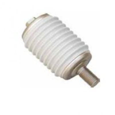
A vacuum circuit breaker can look, sound and operate perfectly and still be unable to interrupt a fault if its interrupter has lost vacuum. This guide explains how maintenance teams verify vacuum integrity in the field, what each test really proves, how to read contact wear and what to do when a pole fails.
Why a Leaking Interrupter Is a Hidden Risk
A healthy vacuum interrupter is sealed at roughly 10-4 Pa or better. At that pressure there is almost nothing between the contacts to ionize, so the arc that forms on contact separation is fed only by metal vapor and goes out at the first current zero. As internal pressure rises, the gap behaves more and more like low-pressure gas: dielectric strength falls and, beyond roughly 10-2 Pa, the interrupter may no longer clear fault current reliably.
The problem is that a ceramic-bodied interrupter gives no outward sign of this. The mechanism still charges, closes and trips. Load current still flows through closed contacts with normal resistance. The defect only shows itself when the breaker is asked to interrupt a fault – and then the result can be a sustained arc, a ruptured pole and an upstream trip that blacks out a whole bus.
Real vacuum loss is rare in modern interrupters, but it does happen. Common causes include:
- Fatigue cracks in the stainless-steel bellows after very high operation counts or mechanism misadjustment (over-travel, bounce).
- Mechanical shock during transport, a dropped truck or poor handling that stresses the ceramic-to-metal brazes.
- Severe overheating of terminals, which can damage seals over time.
- Manufacturing defects that appear early in life (the main reason commissioning tests matter).
Warning Signs Worth Investigating
None of these prove vacuum loss on their own, but each justifies an integrity test on all three poles:
- A failed or delayed fault clearance, breaker-failure protection operating, or evidence of a prolonged arc in fault records.
- Discoloration, tracking or soot on the pole or interrupter housing.
- A pole that runs noticeably hotter than its neighbors on a thermal scan.
- Abnormal noise during switching, or partial discharge readings that rise on one pole.
- Any breaker that has been dropped, flooded or stored for years in poor conditions.
Method 1: Power-Frequency Withstand Across the Open Contacts
This is the standard field check and the one most manufacturers specify. It does not measure pressure; it proves that the open gap can hold a defined voltage, which is what matters in service.
How it is done
- Rack the breaker to the test or withdrawn position, or isolate and earth a fixed breaker following the switching program. Apply lock-out/tag-out.
- Open the breaker and confirm the mechanical position indicator shows OPEN. Discharge the closing spring if the manufacturer requires it.
- Connect the high-voltage lead of an AC test set to one terminal of the pole and earth the other terminal and the frame.
- Raise the voltage steadily to the field test value given in the breaker manual and hold it, typically for one minute.
- Repeat for each pole. A flashover, collapse of voltage or trip of the test set is a failure.
What test voltage to use
Field test values are normally a fraction of the factory value, commonly around 75-80% of the rated short-duration power-frequency withstand voltage across the open gap. That rating depends on the rated voltage and the standard the breaker was built to (IEC 62271-1/-100, national GB standards or ANSI/IEEE C37.06). Always use the figure in the manufacturer’s instructions rather than a generic table; overstressing an aged gap is not a better test.
Safety notes specific to vacuum gaps
- X-radiation. A vacuum gap under high voltage can emit low-level X-rays through field emission. Exposure is negligible at rated test voltages and normal working distance, but keep people out of the test zone and never exceed the specified voltage.
- Prefer AC. DC high-potential tests across a vacuum gap are prone to misleading results because of field-emission currents, and many manufacturers advise against them. If a DC set is the only option, use the manufacturer’s DC value and criteria.
- Earth each terminal after the test; insulation can hold charge.
Method 2: Magnetron (Penning) Pressure Measurement
A magnetron tester estimates the actual internal pressure. A coil placed around the interrupter (or a test fixture holding it) creates an axial magnetic field while a DC voltage of several kilovolts is applied across the open contacts. The crossed fields trap electrons in long spiral paths, so even a few residual gas molecules produce a measurable ion current. The tester converts that current to pressure using a calibration curve for that interrupter type.
| Aspect | Open-gap withstand test | Magnetron test |
|---|---|---|
| What it shows | Gap holds a set voltage: pass/fail | Estimated internal pressure, trendable |
| Equipment | AC hipot set | Dedicated magnetron tester with coils or fixture |
| Access needed | Breaker terminals only | Often interrupter removed from the pole or pole dismantled; embedded poles may not allow it |
| Detects early degradation | No – only once strength has fallen | Yes, if calibration data exist |
| Typical use | Routine maintenance and commissioning | Interrupter supply checks, failure analysis, refurbishment shops |
Typical interpretation, subject to the interrupter maker’s data: pressures around 10-4 Pa or lower are normal for a sound interrupter; readings creeping toward 10-3 Pa indicate degradation worth trending; values approaching 10-2 Pa mean the interrupter should be replaced. Without the correct calibration curve, a magnetron reading is not reliable – this is the method’s main practical limitation.
Method 3: Contact Wear and Main-Circuit Resistance
Vacuum integrity and contact erosion are separate questions, but they are checked together because both decide whether an interrupter stays in service.
Contact wear indicator
Every arc vaporizes a little contact material, so the contacts gradually get shorter. Since the open gap is fixed by the mechanism, erosion shows up as a reduction in contact wipe (the compression of the contact pressure spring when the breaker closes). Most breakers provide a mark, gauge or measurable dimension on the moving stem or push rod. When erosion reaches the limit the manufacturer specifies – often a few millimeters – the interrupter is at end of electrical life even if the vacuum is perfect.
Main-circuit resistance
Measure each pole with a micro-ohmmeter at a DC test current of at least 100 A, as commonly recommended in IEC 62271-1 practice. Compare with the factory value and the other poles. A clear rise points to contact erosion, loose primary connections or damaged cluster contacts on a withdrawable truck; it does not indicate vacuum condition.
How Often to Test
IEC standards leave maintenance intervals to the manufacturer and the user. A sensible default for distribution duty:
- At commissioning: open-gap withstand, contact resistance, timing and wear baseline for every new breaker.
- Every 3-5 years, or at the mechanism service interval: repeat withstand and resistance tests and read the wear indicator.
- After any heavy fault interruption: check wear and resistance and consider a withstand test.
- More often for breakers with very high switching rates (furnace, capacitor and motor duty) – base the interval on operation counter readings, not the calendar.
Condition-monitoring sensors for coil current, travel and temperature, now common on new switchgear, help trigger tests when something changes instead of waiting for a fixed date.
Recording and Acting on Results
Record test voltage, duration, ambient temperature and humidity, wear readings and resistance per pole, together with the operation counter. Trends are more valuable than single numbers.
If a pole fails, remove the breaker from service. Vacuum interrupters cannot be repaired or re-evacuated on site. Replace the interrupter with the exact type approved by the breaker manufacturer – or the complete embedded pole where the interrupter is cast in epoxy – and repeat the full commissioning test set, including timing and contact travel, before returning the breaker to service. For older breakers whose interrupters are no longer available, a modern replacement breaker or retrofit truck is often the faster and safer route.
Frequently Asked Questions
Can vacuum loss be seen through the interrupter body?
Only with old glass-envelope interrupters, where a milky or discolored getter could hint at a problem. Modern interrupters use ceramic bodies, so an electrical test is the only reliable check.
Does an insulation resistance (megger) test prove the vacuum is good?
No. A megger at 2.5 or 5 kV DC tests insulation to earth and may pass across a degraded gap. Use an AC withstand across the open contacts for vacuum integrity.
Is the open-gap test harmful to the interrupter?
Not at the manufacturer’s field value. Repeated tests at excessive voltage, or tests on a gap with contacts not fully open, should be avoided.
What is a normal pressure inside a new interrupter?
Typically around 10-4 Pa or lower at the factory, with sealed designs intended to stay well below the 10-2 Pa region over a service life of 20-30 years.
Work with METTZ Group
METTZ Group offers a wide range of vacuum circuit breakers to suit many needs – from indoor withdrawable VCBs for switchgear panels to outdoor and mining designs, plus replacement vacuum interrupters and embedded poles. Check out our website to learn more, or contact METTZ Group today to work with a representative.
