
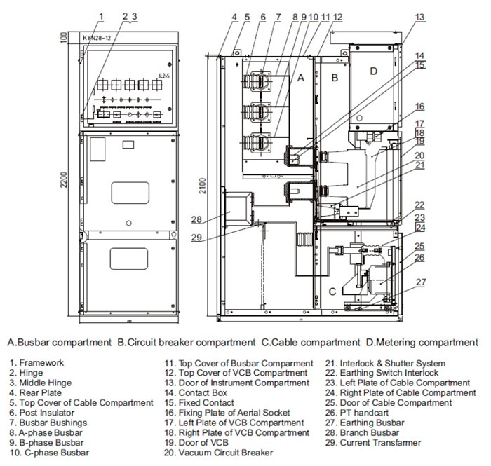
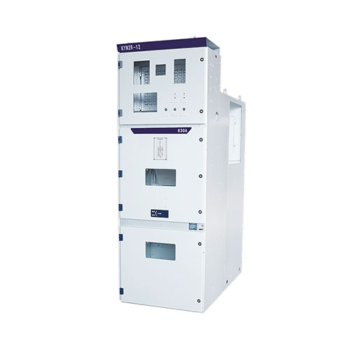
A medium-voltage switchgear panel looks like a plain steel cabinet from the outside, but behind the doors sit four separate worlds: busbars, the switching device, cable connections and secondary control. This guide walks through each compartment, explains what every major component does and shows how they combine to make the panel safe to operate and maintain.
What Counts as an MV Switchgear Panel?
Under IEC 62271-200, metal-enclosed switchgear covers rated voltages above 1 kV and up to and including 52 kV. In practice, most distribution panels are rated 12 kV, 24 kV or 36/40.5 kV, with busbar currents from 630 A to 4,000 A and short-time withstand currents of 20-40 kA for 3 s or 4 s. Industrial plants, utility substations, data centers, mines, solar and wind farms all rely on these panels to distribute power and isolate faults.
Each panel (often called a cubicle or functional unit) performs one job: incoming feeder, outgoing feeder, bus coupler, bus riser, metering, transformer feeder or capacitor feeder. A switchboard is simply a line-up of these units sharing one main busbar. The most common design worldwide is the withdrawable, metal-clad air-insulated switchgear panel, sometimes known by its Russian-language abbreviation KRU, which is what this article describes. Gas-insulated and solid-insulated designs follow the same functional logic in a sealed, more compact form.
The Four Compartments at a Glance
| Compartment | Main contents | Why it is separated |
|---|---|---|
| Busbar compartment | Main busbars, wall bushings, busbar supports | A fault here affects the whole line-up, so it is sealed from operator areas |
| Circuit breaker compartment | Withdrawable truck with vacuum circuit breaker, contact boxes, shutters | Allows the breaker to be racked out and serviced while the busbar stays live |
| Cable compartment | Cable terminations, current transformers, earthing switch, surge arresters, voltage transformers | Gives safe access to cables once the feeder is isolated and earthed |
| Low-voltage compartment | Protection relay, meters, control switches, terminal blocks, auxiliary supply | Keeps secondary wiring and operators away from primary voltage |
1. Busbar Compartment
The main busbar runs horizontally through the top or rear of every panel. It is usually flat or tubular copper, sized for the rated normal current and braced for the peak withstand current (2.5 times the short-time current at 50 Hz under IEC). In larger ratings, bars are often sleeved with heat-shrink insulation to reduce clearances and protect against accidental bridging by small animals or tools.
Where the busbar passes from one panel to the next, it runs through epoxy wall bushings that seal each busbar section. This segregation stops hot gas and arc products from spreading along the line-up during an internal fault. Busbar supports and post insulators hold the conductors at the correct phase spacing, typically 150 mm or more at 12 kV and 210-275 mm at 24 kV, depending on the design and the insulation used.
2. Circuit Breaker Compartment
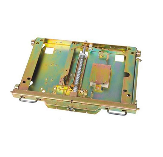
This is the heart of the panel. A wheeled truck carries the vacuum circuit breaker, which can be moved between three positions:
- Service: the breaker’s plug-in contacts engage the fixed contacts in the contact boxes, connecting busbar to cable.
- Test: the primary contacts are separated, but the secondary plug remains connected so the breaker can be closed and opened for functional checks.
- Disconnected/withdrawn: the truck is out of the compartment for inspection or replacement.
Behind the truck sit epoxy contact boxes (spouts) for the upper and lower connections. Metal shutters close automatically over the contact boxes as the truck racks out, so nobody can touch live parts when the compartment door is open. Vacuum interrupters, typically housed in embedded poles, do the actual current interruption, driven by a spring-charged or magnetic operating mechanism.
The breaker trips on current: a protection relay detects overcurrent, earth fault or differential current through the CTs and energizes the trip coil. It does not react to a voltage threshold unless a separate undervoltage release is fitted for a specific purpose.
3. Cable Compartment
The cable compartment is at the bottom or rear of the panel. Typical contents include:
- Cable terminations: heat-shrink or cold-shrink terminations on XLPE cables, bolted to the cable bars. Panels are sized for a stated number of cables per phase.
- Current transformers: ring-type or block-type CTs feed protection relays and meters. Classes are usually 5P or 10P for protection and 0.2 or 0.5 for metering under IEC 61869-2.
- Earthing switch: rated for full short-circuit making capacity, so it is safe even if closed onto a live cable by mistake. It is mechanically interlocked with the breaker truck.
- Voltage transformers and surge arresters: where the feeder needs voltage measurement or protection against switching and lightning surges.
- Voltage presence indication: capacitive dividers in the insulators drive indicator lamps that show whether the cables are live.
4. Low-Voltage Compartment
The top-front relay box holds everything that works at control voltage: multifunction protection relays, energy meters, open/close switches, local/remote selector, indicator lamps, MCBs for auxiliary circuits, terminal blocks and the wiring that ties the panel to SCADA. Modern relays communicate over IEC 61850 or Modbus and can trigger arc-flash tripping, record disturbance data and report breaker wear. Inter-panel wiring runs through a dedicated duct across the top of the line-up.
How the Components Work Together
Normal service
Power enters through the incoming panel, flows along the main busbar and leaves through each outgoing feeder breaker to cables, transformers or motors. CTs and VTs continuously feed measurements to the relays and meters.
Fault clearing
When a short circuit occurs downstream, CT secondary current rises, the relay picks up and sends a trip command. The shunt trip coil releases the opening spring, the contacts in the vacuum interrupter part and the arc extinguishes at the next current zero. Total clearing time for a typical feeder is in the range of 60-100 ms, depending on relay settings and breaker opening time.
Safe isolation for maintenance
A typical sequence is: open the breaker, rack the truck to test position, confirm no voltage on the indicators, close the earthing switch, then open the cable compartment door. Mechanical interlocks enforce this order. The truck cannot move while the breaker is closed, the earthing switch cannot close while the truck is in service position, and the cable door cannot open until the earthing switch is closed.
Key Classifications to Check on Any Panel
| Item (IEC 62271-200) | What it means | Typical choice |
|---|---|---|
| LSC (loss of service continuity) | How much of the switchboard stays live when one compartment is opened | LSC2B for withdrawable metal-clad panels |
| Partition class | PM = metallic partitions and shutters; PI = insulating partitions | PM for metal-clad designs |
| IAC (internal arc classification) | Tested protection of people during an internal arc, e.g. IAC AFLR 31.5 kA 1 s | A for authorized staff; F, L, R for front, lateral and rear sides |
| IP rating (IEC 60529) | Protection against solid objects and water | IP4X enclosure, IP2X between compartments |
Pressure relief flaps on each compartment open upward during an internal arc and vent the gas into an arc duct or the room ceiling area, away from the operator. Where the room is small, an arc channel exhausting outside the building is the safer option.
How MV Panels Differ from LV and HV Equipment
Low-voltage switchboards (up to 1 kV AC under IEC 61439) rely on air or moulded-case breakers and usually allow more open busbar construction. High-voltage equipment above 52 kV is mostly outdoor AIS or GIS with live-tank or dead-tank breakers and separate disconnectors. The MV panel sits between them: compact, factory-assembled, type-tested as a whole and designed so the switching device itself provides the isolation point when racked out.
Trends in 2026
- SF6-free designs: the EU F-gas Regulation (EU) 2024/573 phases out SF6 in new MV switchgear, pushing buyers towards vacuum breakers with air, dry air or solid insulation.
- Digital panels: low-power instrument transformers (IEC 61869-10/-11), wireless temperature sensors on contacts and cable joints, and partial discharge monitoring are becoming standard options.
- Arc-flash mitigation: optical arc sensors and fast-acting earthing devices cut arc duration to a few milliseconds.
- Renewables and data centers: higher fault levels and frequent switching demand E2/M2 class breakers and robust contact systems.
Frequently Asked Questions
What is the difference between metal-clad and metal-enclosed switchgear?
Metal-clad is a subset of metal-enclosed switchgear in which the switching device is withdrawable and each main compartment is separated by earthed metal partitions and shutters (partition class PM).
Why does a switchgear panel need an earthing switch if the breaker is already open?
An open breaker does not discharge a cable or protect against back-feed. The earthing switch connects the conductors to earth so staff can work safely on cables and terminations.
Can a vacuum circuit breaker be replaced without shutting down the busbar?
Yes, in a withdrawable panel with LSC2B classification the truck can be racked out and replaced while the busbar and neighboring feeders remain in service.
Which components wear out first?
Mechanical parts of the operating mechanism, auxiliary switches and plug-in contacts need the most attention. Vacuum interrupters and epoxy parts usually last the life of the panel if kept within rating.
Work with METTZ Group
METTZ Group offers a wide range of medium-voltage switchgear and switchgear components to suit many needs – from complete withdrawable panels for utility substations to vacuum interrupters, embedded poles and coils for panel builders and maintenance teams. Check out our website to learn more, or contact METTZ Group today to work with a representative.
