
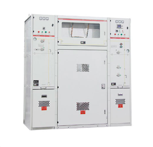
Gas-insulated switchgear is designed to run for decades with little attention, but only if it is installed cleanly and commissioned properly. This guide walks through the sequence used on real projects: site readiness, receiving inspection, assembly, evacuation and gas filling, on-site tests and the first energization.
Why installation quality decides GIS reliability
Most GIS faults that appear in the first years of service trace back to the site, not the factory. A speck of metal dust on an insulator, a damaged O-ring, moisture left in a compartment or a misaligned flange can all lead to partial discharge and, eventually, a flashover. Because the switchgear is sealed, these defects stay hidden until they cause trouble.
The process differs by voltage level:
- MV GIS (up to 40.5/52 kV, IEC 62271-200) is usually shipped as factory-filled, sealed panels. Site work is mostly positioning, busbar coupling, cable termination and testing; opening gas compartments on site is rare.
- HV GIS (above 52 kV, IEC 62271-203) arrives as transport units that are joined on site. Flanges are opened, conductors are plugged together and each compartment is evacuated and filled. Cleanliness and gas handling become critical.
The steps below apply to both, with the gas-related steps mainly relevant to HV.
Step 1: Planning and document review
Before anything arrives on site, the installation team should have and understand:
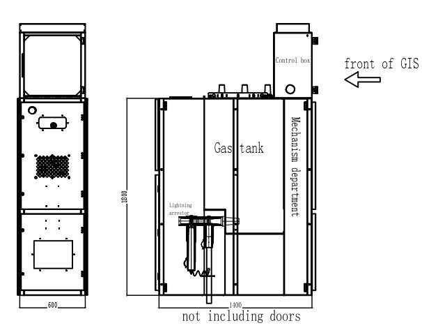
- General arrangement and foundation drawings, single-line diagram and gas compartment (gas zone) diagram.
- The manufacturer’s erection manual, tightening torques, lifting instructions and the list of special tools.
- The commissioning test plan with acceptance values, agreed with the client and the network operator.
- A gas handling plan covering filling quantities, gas certificates (IEC 60376 for new SF6 or the supplier’s data for alternative gases), recovery equipment and record keeping.
- Safety documents: method statements, risk assessment, permit-to-work and lockout/tagout procedures for any adjacent live equipment.
Assign named, trained people for assembly, gas work and testing. In the EU, personnel who recover or handle fluorinated gases in switchgear must hold certification under the F-gas Regulation (EU) 2024/573.
Step 2: Site and building readiness
GIS should be installed into a finished, dry and clean room, not into a construction site. Check that:
- Civil works, painting, ceiling work and drilling are complete; floors are sealed to limit dust.
- Foundation frames or embedded steel channels are level and in line within the manufacturer’s tolerance, typically a few millimetres over the full line-up.
- Cable trenches, floor openings and pressure-relief routes match the drawings, and the room meets internal arc requirements (IAC classification, venting paths).
- The overhead crane or lifting gear is certified and rated for the heaviest transport unit.
- Ventilation is available at floor level and in cable basements, because SF6 is about five times heavier than air and collects in low spaces.
- The earthing grid is installed and tested before equipment is placed.
For outdoor HV GIS, plan weather protection: temporary tents or clean houses over open flanges, and a rule that no compartment is opened in rain, wind-blown dust or high humidity.
Step 3: Receiving inspection
Check every transport unit on arrival, before it is unloaded if possible:
- Read the shock (impact) recorders fitted for transport and record the values. Any reading above the manufacturer’s limit should be reported before assembly continues.
- Confirm that transport units still hold their dry-air, nitrogen or low-pressure gas filling, which shows the seals survived shipping.
- Inspect for dents, damaged paint, broken gauges and loose fittings; compare packing lists with the delivery.
- Store parts indoors, in their packaging, off the floor. Keep insulators, conductors and seals sealed until the moment of use.
Step 4: Mechanical assembly
Assembly follows the sequence in the erection manual, usually starting from a reference bay and working outward.
Positioning and alignment
Set the first bay on its marked position, level it and fix it. Align following bays to it using the specified shims and alignment pins. Do not force flanges together: misalignment puts mechanical stress on cast-resin insulators.
Clean-room practice at open flanges
- Open a compartment only when ready to connect it, and close it as quickly as possible.
- Wear lint-free clothing, gloves and shoe covers; use a vacuum cleaner with a fine filter, never compressed air.
- Clean flange faces, conductor contacts and insulator surfaces with lint-free wipes and the solvent approved by the manufacturer.
- Fit new O-rings every time a flange is opened, and apply grease only where specified.
- Replace desiccant (molecular sieve) bags just before closing the compartment.
Bolting and connections
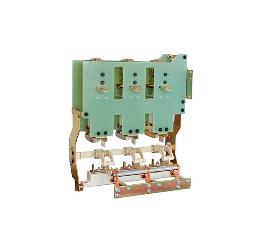
Tighten flange bolts crosswise in stages to the specified torque and mark each bolt. Connect plug-in conductors, operating mechanisms, gas pipework and density monitors, then install secondary wiring between bays and to the control cabinets.
Step 5: Evacuation and gas filling
Each newly closed HV compartment is evacuated before filling. A typical sequence is:
- Evacuate with a gas service cart to the pressure set by the manufacturer, often around 1 mbar or lower.
- Hold the vacuum for a defined time and check the pressure rise. A fast rise points to a leak or moisture still evaporating.
- Fill with certified gas through a filter, to the rated filling pressure corrected for the actual gas temperature. Use the density, not the pressure reading alone.
- Record the mass of gas added to each compartment, the cylinder numbers and the operator. These records are needed for F-gas compliance and future leak tracking.
Never vent SF6 to the atmosphere. Recover it with a certified cart and reuse it according to IEC 60480. More detail on safe handling is in our guide to SF6 leak detection and gas safety.
Step 6: On-site tests
After filling, allow time for moisture to equalize (often 24 hours or more) before measuring gas quality. The test programme in IEC 62271-203 and the manufacturer’s instructions typically includes:
| Test | What it proves |
|---|---|
| Gas tightness check (sniffer or accumulation method) | Site-made flanges and pipework do not leak |
| Gas quality: moisture, purity, decomposition products | Gas is dry and clean enough for dielectric and switching duty |
| Main circuit resistance (micro-ohm) | Plug-in contacts and bolted joints are properly made |
| Mechanical operation and timing of breakers, disconnectors and earthing switches | Mechanisms work, with correct speed and synchronism |
| Interlock and control logic checks, point-to-point wiring | Unsafe operations are blocked; signals reach the right place |
| Density monitor alarm and lockout settings | Alarms trigger at the right gas density |
| CT and VT checks (ratio, polarity, insulation) | Protection and metering get correct signals |
| Power-frequency voltage test on the main circuit, often with partial discharge measurement (UHF or IEC 60270) | The assembled insulation is free of defects |
The on-site voltage test is normally performed at a reduced level, commonly 80% of the rated short-duration power-frequency withstand voltage, so that the test does not overstress healthy insulation. Partial discharge monitoring during the test helps locate particles or loose parts before they cause a flashover.
For MV GIS, the usual site checks are insulation resistance, main circuit resistance at busbar joints, a power-frequency or VLF test of cables, mechanical operation, interlocks and protection relay tests.
Step 7: Energization and handover
- Remove all temporary earths and test equipment; confirm that every compartment shows normal density.
- Issue the energization permit, energize in the agreed sequence and observe for a soak period with no load.
- Check for abnormal noise, partial discharge alarms and temperature rise, then load progressively.
- Hand over the as-built drawings, test reports, gas records and setting lists, and train the operators.
Re-check gas density trends after the first weeks of service. Online density and partial discharge monitoring, increasingly delivered through IEC 61850 substation automation, make this simple.
Common mistakes to avoid
- Installing before the room is finished and dust-free.
- Reusing old O-rings or skipping the vacuum hold test to save time.
- Filling by pressure without temperature correction.
- Measuring moisture immediately after filling, before the gas has settled.
- Missing gas records, which later makes leak tracking and F-gas reporting impossible.
Frequently Asked Questions
How long does GIS commissioning take?
For a few MV panels, site work and testing can take days. A multi-bay HV GIS substation usually needs several weeks for assembly, gas work and testing, depending on the number of bays and the test programme.
Does MV GIS need gas filling on site?
Usually not. Most MV GIS panels are filled and sealed in the factory. Site work focuses on busbar coupling, cable connections and tests.
Why is the on-site voltage test lower than the factory test?
Each part was already type- and routine-tested at full level. The site test at a reduced level, typically 80%, checks the assembly for site-introduced defects without overstressing the insulation.
Do SF6-free GIS need a different procedure?
The overall sequence is the same. Filling pressures, gas analysis methods and handling equipment depend on the gas used, so follow the manufacturer’s instructions for that gas.
Work with METTZ Group
METTZ Group offers a wide range of gas-insulated switchgear to suit many needs – from compact MV panels for distribution substations to complete switchgear solutions for industrial plants, mining and projects in tropical climates – with design, supply and commissioning support through local partners. Explore our substations and medium-voltage switchgear ranges on our website, or contact METTZ Group today to work with a representative.
