
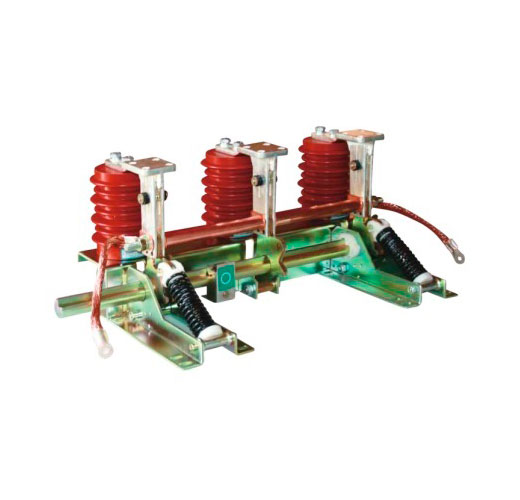
Most serious switching accidents in medium-voltage substations follow the same pattern: an earthing switch closed onto a live circuit, or a circuit energized while still earthed. Interlocks and disciplined switching sequences exist to make those mistakes impossible. This article explains how earthing switch interlocks work, the sequence to follow, and how to keep the whole system reliable through maintenance.
The Two Mistakes Interlocks Must Prevent
An earthing switch is only safe when it is used at the right moment. Two errors cause most incidents:
- Earthing a live circuit. The earthing switch closes while the main switching device is closed or the cable is still fed from the remote end. The result is a bolted three-phase fault at the operator’s position.
- Energizing an earthed circuit. The breaker or load break switch is closed while the earthing switch is still closed. Again, a full short circuit, often after a long maintenance job when people are tired and in a hurry.
A third, quieter danger is opening a compartment door while the conductors behind it are live. IEC 62271-200 addresses all three by requiring interlocks between the components of MV switchgear and by defining which compartments may be opened only when the circuit is isolated and earthed (interlock-controlled accessible compartments).
Types of Earthing Switch Interlocks
Mechanical interlocks
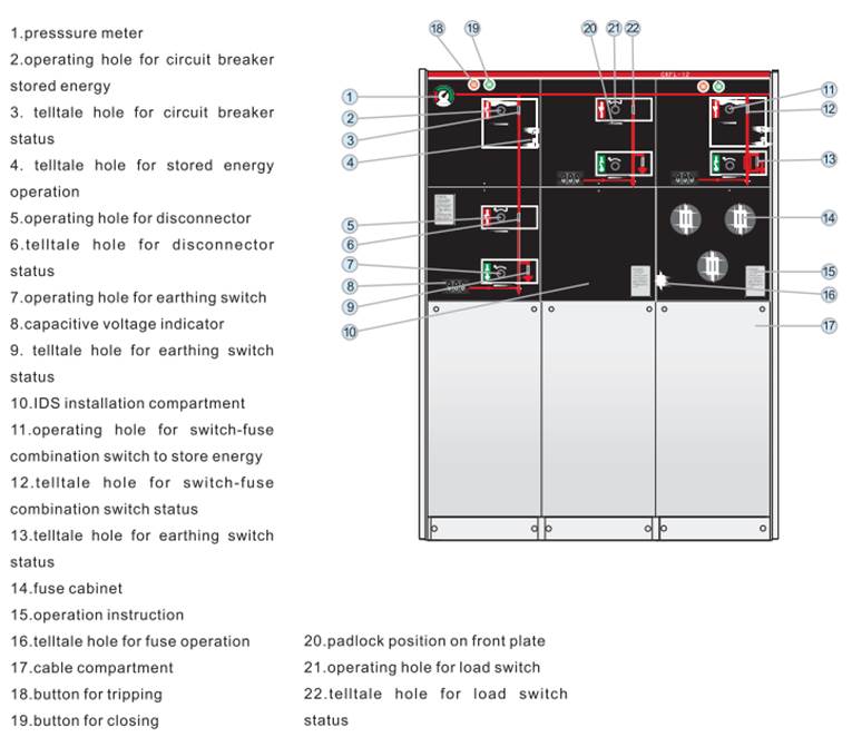
Mechanical interlocks are the first line of defence because they work without auxiliary power. Typical examples in MV panels and ring main units:
- The earthing switch operating shaft is blocked while the associated load break switch or circuit breaker is closed.
- In a three-position switch (closed – open – earthed), the moving contact physically cannot go from “closed” to “earthed” without passing through “open”. One mechanism, one contact system, no way to have both closed at once.
- A withdrawable circuit breaker can only be racked in or out when it is open, and the earthing switch can only be closed when the breaker truck is in the test or disconnected position.
- The cable compartment cover can only be removed when the earthing switch is closed, and the earthing switch cannot be opened while the cover is off.
- In switch-fuse units, the fuse compartment opens only when the earthing switches on both sides of the fuses are closed.
Key interlocks
Mechanical linkages only work inside one panel. When the safety logic spans several devices, such as a ring cable with switchgear at both ends, or an MV switch and an LV transformer breaker, trapped-key interlocks transfer the logic. A key is trapped in a lock while a device is in the “unsafe” position and released only when it reaches the “safe” position. That key is then needed to operate the next device in the sequence.
A typical transformer scheme: opening the LV main breaker releases key A; key A is needed to open the MV switch, which releases key B; key B unlocks the MV earthing switch and, later, the transformer enclosure door. The sequence can only be performed in one order, and reversed only in the opposite order.
Electrical interlocks
Motor-operated and remotely controlled switchgear adds electrical interlocks: auxiliary contacts and blocking coils that prevent the closing command unless the conditions are met. Many modern panels also use voltage presence signals to block earthing when voltage is detected on the cable. Electrical interlocks are valuable for remote operation, but they depend on auxiliary supply and wiring, so they should supplement, not replace, mechanical interlocks.
Padlocks and lockout
Every earthing switch should have padlocking facilities in both the open and earthed positions. Padlocks do not replace interlocks. They implement the “secure against reconnection” step of the safety procedure and identify who is working on the circuit.
The Correct Switching Sequence
Local safety rules always take precedence, but most follow the logic of the “five safety rules” of EN 50110-1. Applied to an MV cable feeder, a safe sequence looks like this:
| Step | Action | Why it matters |
|---|---|---|
| 1 | Open the circuit breaker or load break switch | Interrupts load current with a device rated to do so |
| 2 | Isolate: rack out the breaker or open the disconnector, and isolate the remote end of the cable | Creates a reliable isolating distance from every source |
| 3 | Lock and tag all isolating points | Prevents reconnection by others |
| 4 | Verify absence of voltage on all phases | Confirms isolation; test the indicator on a known live source first |
| 5 | Close the earthing switch | Connects all phases together and to earth |
| 6 | Apply additional portable earths at the work location if required | Protects against induced voltage and remote backfeed |
| 7 | Protect against adjacent live parts | Barriers, shutters and safe working distances |
Restoration is the exact reverse: remove portable earths, account for every person and tool, open the earthing switch, remove locks, and only then re-energize. Most “energized while earthed” accidents happen because portable earths were forgotten, not because the switchgear earthing switch was left closed.
Verification of absence of voltage
Modern MV switchgear has a voltage presence indicating system (VPIS) according to IEC 62271-213, with indicator lamps or test sockets on the panel front. Use it every time, on every phase. A dark indicator could be a failed lamp, which is why the indicator should be checked before and after the test.
Special Situations
- Ring cables. The cable must be isolated at both ends before earthing. If the remote substation is not covered by your key system, a written permit and physical confirmation are essential. This is also why E2 making class is recommended for RMU earthing switches.
- Cable testing. High-voltage cable tests require the earth to be removed from the cable core while the test set is connected. Use the manufacturer’s test-access procedure and a dedicated test permit, and re-earth before disconnecting the test leads.
- Distributed generation. PV plants, wind turbines and battery systems can backfeed a feeder. Their isolation points must be part of the switching programme.
- Capacitor banks. Allow the specified discharge time before earthing, then earth.
Maintaining Earthing Switches and Interlocks
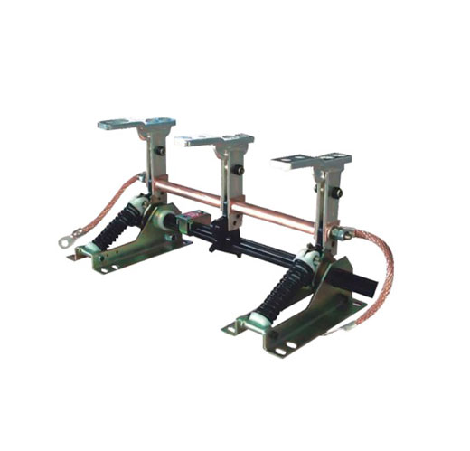
Earthing switches spend most of their life idle, and that is exactly the problem: grease hardens, linkages seize and interlocks drift out of adjustment without anyone noticing. Always follow the manufacturer’s manual. The plan below is a typical starting point.
| Task | Typical interval | What to look for |
|---|---|---|
| Visual inspection | During routine substation visits | Position indicator matches the mimic; no corrosion, damage, overheating marks or loose earth braids |
| Operation test | Annually, or at each planned outage | Smooth closing and opening, full travel, spring mechanism snaps correctly |
| Interlock function test | Annually and after any modification | Every interlock blocks the wrong operation; try each forbidden sequence deliberately (with the circuit dead) |
| Main contact resistance | Per manufacturer, often every 3-6 years | DC micro-ohm measurement at 100 A or more, compared with factory values |
| Lubrication and cleaning | Per manufacturer | Only approved lubricants; remove old grease and dust from linkages |
| Earth connection check | With operation test | Tight, intact connection from the earthing switch to the substation earthing system |
| Auxiliary contacts and signals | With operation test | Correct position signal at the RTU or SCADA; blocking coils work |
Sealed gas-insulated and solid-insulated units need less work on the contacts themselves, but their external mechanisms, interlocks and indicators still need regular functional checks.
Record keeping
Log every operation, test result and repair with the date, operator and readings. Trends in contact resistance or operating force reveal problems long before a failure. After any event where an earthing switch closed onto a live circuit, take the switch out of service for inspection according to its making class and the manufacturer’s instructions.
Frequently Asked Questions
Can I bypass an interlock to finish a job faster?
No. Interlock defeats are a leading cause of arc-flash injuries. If an interlock blocks you, it is telling you the sequence is wrong or the equipment is faulty. Stop and investigate.
Are mechanical interlocks required by IEC 62271-200?
The standard requires interlocks between switching devices and earthing switches, and for interlock-controlled compartments, between the cover and the circuit condition. Mechanical interlocks are the usual way to meet these requirements.
How often should earthing switches be operated?
At least once a year if they are not used in normal work, so the mechanism stays free and interlocks are proven. Follow the manufacturer’s recommendations.
Do key interlocks work across two substations?
Yes, but it requires disciplined key management. Many utilities use permits and remote position confirmation instead.
Work with METTZ Group
METTZ Group offers a wide range of earthing switches to suit many needs – from interlocked indoor units for MV panels to outdoor and mining-duty designs, together with load break switches and complete medium-voltage switchgear with built-in interlocking. Check out our website to learn more, or contact METTZ Group today to work with a representative.
