
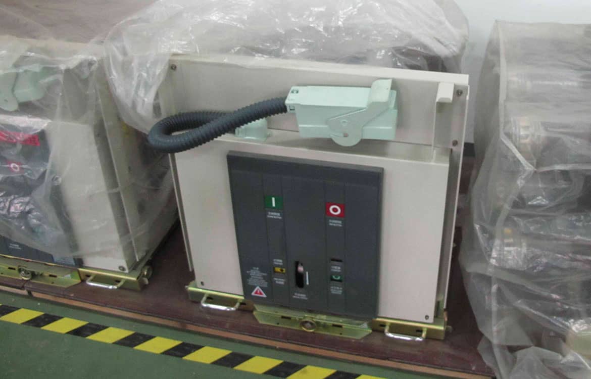
Most vacuum circuit breaker problems seen in the first year of service trace back to transport, storage or commissioning shortcuts rather than to the breaker itself. This guide walks through the full sequence – receiving, storage, mounting, connections, earthing, testing and energization – with the checks that matter at each stage.
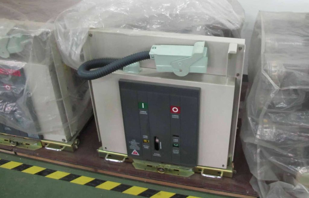
Step 1: Receiving Inspection
Inspect every crate on arrival, before signing the delivery note.
- Check shock and tilt indicators on the packaging; record any that have triggered.
- Look for crate damage, moisture inside the packaging and loose parts.
- Compare each nameplate with the order: rated voltage, rated normal current, short-circuit breaking current, auxiliary and control voltages, mechanism type and frame size.
- Confirm that manuals, routine test reports, keys, racking handles, charging levers and spare parts are present.
- Photograph any damage and notify the supplier and carrier in writing straight away.
Step 2: Storage Until Installation
VCBs are often delivered weeks before the switchroom is ready. Poor storage causes condensation in mechanisms, corrosion of contacts and contamination of insulation.
- Store indoors, on a level and dry floor, in the original packaging, in an area free from dust, corrosive vapors and construction work.
- Keep within the temperature range given by the manufacturer and avoid large daily swings that cause condensation. Use space heaters if needed.
- Store breakers in the OPEN position with closing springs discharged.
- For long storage, inspect periodically and follow the manufacturer’s instructions for mechanism exercise and lubrication before commissioning.
Step 3: Site and Room Readiness
Do not install breakers into an unfinished room. Check that:
- Civil works, plastering, painting and floor grinding are complete; dust is the enemy of insulation and mechanisms.
- The room meets the service conditions on the switchgear datasheet. IEC 62271-1 normal indoor conditions include a maximum ambient of 40 °C, altitude up to 1,000 m and limits on humidity; anything outside that needs a derated or special design.
- Floor channels and base frames are level within the switchgear manufacturer’s tolerance – a twisted frame makes racking difficult and misaligns primary contacts.
- Ventilation, lighting, cable trenches and, for arc-classified switchgear, pressure-relief ducts are in place.
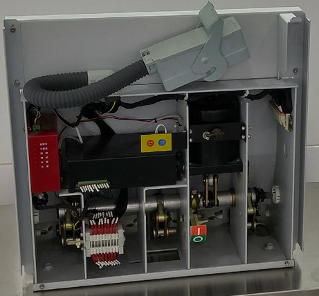
Step 4: Handling and Mounting
Use the lifting points and handling trolley specified by the manufacturer. Never lift a breaker by its poles, interrupters, bushings or mechanism cover.
Withdrawable breakers
- Align the service trolley with the panel and transfer the breaker onto the rails.
- Rack it from the disconnected to the test position and back, by hand, before connecting anything. The movement should be smooth with no binding.
- Check that shutters open and close correctly and that the breaker cannot be racked in while closed.
- Check the engagement of the primary cluster contacts (many manufacturers specify a contact-mark or penetration check).
Fixed breakers
- Fix the breaker to its frame with the specified bolts and torque; check that the frame does not distort.
- Verify clearances to earthed parts and phase-to-phase distances against the drawings.
Step 5: Primary Connections
- Clean contact surfaces and apply contact compound only if the manufacturer specifies it.
- Use the specified bolt grade, washers and torque for each joint, and mark tightened bolts.
- Make sure busbars and cable terminations do not apply mechanical load to the breaker terminals.
- Keep phase sequence and phase identification consistent with the single-line diagram.
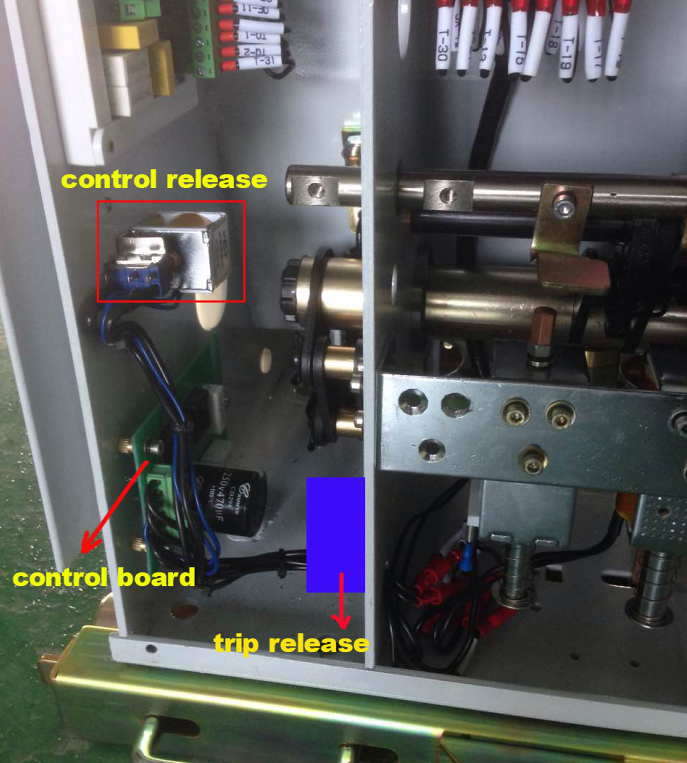
Step 6: Secondary Wiring and Control Integration
- Connect the secondary plug or terminal blocks following the schematic; check every wire number.
- Measure the auxiliary supply at the breaker before connecting the motor and coils. Wrong control voltage is one of the most common commissioning faults.
- Integrate trip circuits with the protection relay, including trip-circuit supervision where specified.
- Wire remote open/close, position indication and spring-charged status to the SCADA or station controller and test each signal end to end.
Step 7: Earthing
Connect the breaker frame, truck earthing contact and panel earth bar to the station earthing system with conductors of the specified cross-section. Check continuity from the breaker frame to the main earth bar with a low-resistance ohmmeter. Poor earthing creates touch-voltage hazards during faults and can upset protection and secondary electronics.
Step 8: Pre-Commissioning Tests
The table below lists the usual site tests. Use the manufacturer’s acceptance values and the project’s inspection and test plan; the factory routine test report is the baseline for comparison.
| Test | Purpose | Typical acceptance basis |
|---|---|---|
| Visual and mechanical inspection | Damage, missing parts, correct labelling | No defects; counter reading recorded |
| Manual operation | Mechanism moves freely | Charge, close and open by hand smoothly |
| Insulation resistance | Main circuit to earth and between phases; secondary circuits | Manufacturer’s minimum, typically in the gigaohm range for primary |
| Main-circuit resistance | Contacts and joints | Within the factory value tolerance; poles similar |
| Power-frequency withstand | Dielectric integrity, including across open contacts | Field value from the manual, typically a reduced percentage of the factory value |
| Timing and travel | Opening, closing, pole synchronism, bounce | Within the manufacturer’s limits |
| Minimum operating voltage | Coils and motor operate at reduced supply | IEC 62271-1 ranges, e.g., shunt opening releases from 70% (DC) of rated supply voltage; closing releases from 85% |
| Spring charging time | Motor and gearbox health | Within datasheet time |
| Anti-pumping | Breaker does not repeatedly close onto a fault | One close only with a sustained close command and trip signal |
| Interlocks | Safety of operators | All mechanical and electrical interlocks work as designed |
Step 9: Protection and Functional Tests
- Inject secondary current into the protection relay and confirm the breaker trips on each protection function, including breaker-failure where fitted.
- Check that the current transformer polarity and ratio are correct and that relay settings match the approved settings file.
- Test local, remote and SCADA open/close, plus all alarms and indications.
- For auto-reclosing feeders, test the full reclose sequence.
Step 10: First Energization
- Remove all temporary earths, tools and test leads; close all doors and covers.
- Issue a formal permit and switching program; brief everyone involved and clear the area.
- Rack the breaker into service using remote racking where available.
- Close remotely. Check voltages, phase sequence and absence of abnormal noise or partial discharge.
- Apply load gradually and perform a thermal scan of connections after a few hours at significant load.
Step 11: Documentation and Handover
Hand over a complete file: signed test sheets with instrument serial numbers, as-built schematics, relay settings, counter readings, timing traces and the maintenance schedule. These records are the reference for every future test, so store them where maintenance teams can find them.
Frequently Asked Questions
What should be done if a VCB will not close during commissioning?
Check, in order: spring charged indication, control supply at the coil, closing interlocks (racking position, earthing switch, door, undervoltage release), anti-pumping relay state and the closing coil itself. Most cases are interlock or wiring issues.
Is a power-frequency test across open contacts necessary at site?
It is strongly recommended. It is the simplest check that the interrupters have not lost vacuum during transport and storage.
How long can a VCB be stored before installation?
Typically many months in dry indoor storage. For long periods, follow the manufacturer’s storage instructions and repeat mechanism checks before use.
Work with METTZ Group
METTZ Group offers a wide range of vacuum circuit breakers to suit many needs – from indoor breakers for medium-voltage switchgear to outdoor and mining designs – with supply and commissioning support through local partners. Check out our website to learn more, or contact METTZ Group today to work with a representative.
