
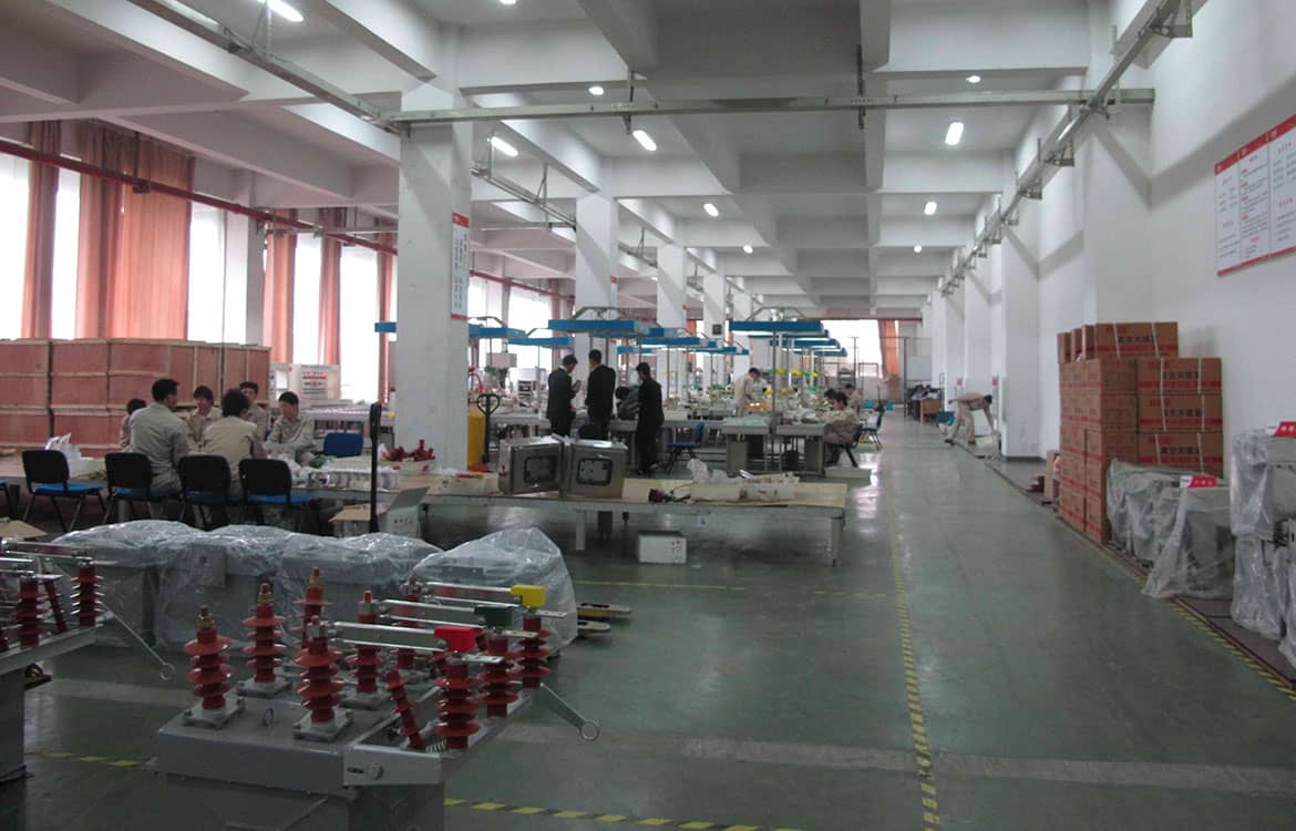
Most switchgear problems found on site trace back to the purchase order: a missing rating, an unverified type test or an interface nobody checked. This checklist takes procurement and engineering teams step by step through what to specify, what to ask suppliers for and what to verify before components ship.
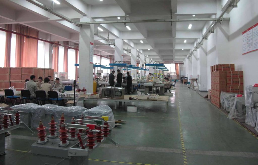
Why a Checklist Matters
Switchgear components are bought in many ways: as complete panels, as kits for local assembly, or as individual parts such as breakers, vacuum interrupters, contact boxes and current transformers. Each route has the same risk. If one rating or interface is wrong, the equipment either fails a site test or, worse, passes and fails years later under fault conditions. A structured checklist keeps engineering, purchasing and quality control working from one set of requirements.
Step 1: Define the System Data
Collect these values before requesting quotations. Every component rating flows from them.
- Rated voltage (Ur): the highest system voltage, for example 12, 24, 36/40.5, 72.5 or 145 kV, not the nominal 10, 20 or 35 kV.
- Insulation level: power-frequency and lightning impulse withstand values from IEC 62271-1 (for example 28/75 kV at 12 kV, 50/125 kV at 24 kV, 70/170 kV at 36 kV), or the higher values some national grids require.
- Rated normal current: for busbars and each feeder, with ambient temperature and any derating for altitude or enclosure.
- Short-circuit level: short-time withstand current and duration (for example 25 kA 3 s), peak withstand current and, for breakers, breaking current and DC component.
- System earthing: solidly earthed, resistance earthed, compensated or isolated. It affects surge arrester ratings and CT selection.
- Environment: indoor or outdoor, altitude above 1,000 m, temperature range, humidity and condensation, pollution, seismic zone, tropical or mining duty.
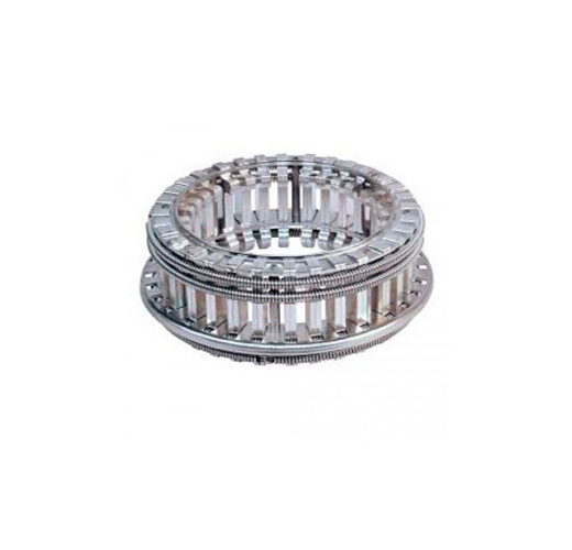
Step 2: List the Core Primary Components
| Component | Key ratings to specify | Main standard |
|---|---|---|
| Circuit breakers | Ur, Ir, Isc, operating sequence, E/M/C classes, mechanism type and coil voltages | IEC 62271-100 |
| Disconnectors and earthing switches | Ur, Ir, short-time current, making capacity of earthing switch, M and E classes | IEC 62271-102 |
| Load break switches and fuse combinations | Mainly active load breaking, transfer current, fuse rating | IEC 62271-103, IEC 62271-105, IEC 60282-1 |
| Current transformers | Ratio, burden, accuracy class (0.2S, 0.5, 5P20), thermal and dynamic rating | IEC 61869-2 |
| Voltage transformers | Ratio, accuracy class, burden, fused or unfused | IEC 61869-3 |
| Surge arresters | Continuous operating voltage Uc, nominal discharge current, energy class | IEC 60099-4 |
| Busbars and connectors | Cross-section, material, plating, temperature rise, phase spacing | IEC 62271-1, -200 |
| Bushings, contact boxes, post insulators | Ur, Ir, creepage distance, partial discharge level | IEC 60137, IEC 60660 |
For an assembled panel, the whole medium-voltage switchgear unit must be type-tested to IEC 62271-200 (MV) or IEC 62271-203 (GIS above 52 kV). Components tested in a different enclosure do not automatically carry their ratings over.
Step 3: Secondary, Control and Monitoring Items
- Protection relays with the required functions (50/51, 50N/51N, 67, 87, 27/59, 81) and communication protocol (IEC 61850, Modbus, DNP3).
- Auxiliary supply voltage for closing coils, trip coils and spring-charging motors: 24, 48, 110 or 220 V DC, or 230 V AC.
- Control switches, local/remote selectors, indicator lamps and mimic diagram.
- Auxiliary contacts: number of spare normally open and normally closed contacts on the breaker and switches.
- Remote monitoring interfaces: temperature sensors, partial discharge sensors, SF6 or gas density monitors where applicable, breaker condition data.
- Wiring standard: wire sizes, color code, ferrules, terminal type and labeling language.
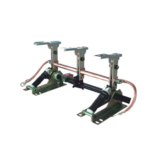
Step 4: Safety Features and Interlocks
- Mechanical interlocks between breaker truck, earthing switch and doors, plus key interlocks for multi-panel sequences.
- Internal arc classification: IAC class (A or B), accessible sides (F, L, R) and test current and duration, for example IAC AFLR 25 kA 1 s.
- Pressure relief and arc ducts compatible with the room layout and ceiling height.
- Voltage presence indication to IEC 62271-213 on cable compartments.
- Padlocking provisions for lockout/tagout on racking openings, earthing switch handles and shutters.
- Arc-flash detection (optical sensors linked to relays) where fast clearing is required.
Step 5: Materials and Build Quality
- Epoxy parts: made by automatic pressure gelation (APG) or vacuum casting, free of voids, with a stated partial discharge level, typically a few picocoulombs at the test voltage.
- Conductors: electrolytic copper (or aluminum where approved), with silver or tin plating on joints and contacts.
- Enclosure: aluminum-zinc coated or galvanized steel, typically 2-2.5 mm, or stainless steel for coastal sites. Powder coating thickness and color code (for example RAL 7035).
- Degree of protection: IP rating to IEC 60529, typically IP4X indoor and IP54 or higher outdoor.
- Severe climatic conditions: for humid or polluted indoor rooms, refer to IEC TS 62271-304 and ask for heaters, anti-condensation measures and longer creepage distances.
Step 6: Supplier Evaluation and Documents
Ask every bidder for the same document set so offers can be compared fairly:
- Type test reports from an accredited laboratory covering the exact design and ratings offered (dielectric, temperature rise, short-time and peak current, breaking and making, mechanical endurance, internal arc).
- Routine test procedure and sample routine test report.
- Quality management certificate and inspection and test plan (ITP).
- General arrangement and foundation drawings, single-line and schematic diagrams, bill of materials.
- Operation and maintenance manual, recommended spare parts list and tool list.
- Material and plating certificates for critical parts where your specification requires them.
Read type test reports carefully. Check that the tested voltage, current, short-time duration and IAC values match or exceed your requirements, and that the report applies to the same enclosure size and component arrangement.
Step 7: Factory Acceptance and Site Testing
| Test | At the factory (FAT) | On site (SAT) |
|---|---|---|
| Power-frequency withstand of main circuit | Yes, full routine value | Often at reduced value after installation |
| Main circuit resistance | Yes | Yes, compare with FAT values |
| Mechanical operation and interlocks | Yes | Yes |
| Secondary wiring and functional checks | Yes | Yes, with relays set to final settings |
| Partial discharge | On epoxy parts and, where specified, on panels | Optional, useful as a baseline |
| CT and VT checks (ratio, polarity) | Yes | Yes, including primary injection |
Step 8: Logistics, Spares and Lifecycle
- Packing for sea freight: seaworthy crates, desiccant and moisture barrier, shock indicators for breakers and instrument transformers.
- Lead time and delivery terms (Incoterms), including partial deliveries for phased projects.
- Spare parts for at least the commissioning period and the first years of operation: trip and close coils, auxiliary switches, charging motors, fuses, contact fingers and indicator lamps.
- Availability of replacement vacuum interrupters, embedded poles and coils for the expected service life.
- Training for operators and maintenance staff, and commissioning support.
Common Mistakes to Avoid
- Specifying nominal voltage instead of rated voltage, or forgetting altitude correction above 1,000 m.
- Accepting component type tests as proof of panel performance.
- Undersizing CTs so they saturate during faults and protection fails to operate correctly.
- Ignoring the internal arc venting route in the switch room design.
- Leaving the coil and motor voltages undefined until after the order.
- Choosing SF6 equipment without checking local F-gas rules that may restrict new installations.
Frequently Asked Questions
Is a factory acceptance test mandatory?
Routine tests are mandatory under IEC 62271. Witnessing them as a formal FAT is a buyer’s choice, but it is strongly recommended for critical projects.
Can MV components from different suppliers be combined in one panel?
Yes, but the combined panel must then be verified by type tests for that arrangement. Interfaces such as contact box sizes, phase spacing and truck dimensions must match exactly.
Which spares should be ordered with the switchgear?
At minimum: trip and closing coils, a charging motor, auxiliary switches, fuses for VTs and control circuits, and indicator lamps. Large sites often keep a spare breaker truck.
Work with METTZ Group
METTZ Group offers a wide range of switchgear components and mechanisms to suit many needs – from vacuum interrupters and embedded poles to complete vacuum circuit breakers and panels for 1 kV to 220 kV networks. Check out our website to learn more, or contact METTZ Group today to work with a representative.
