
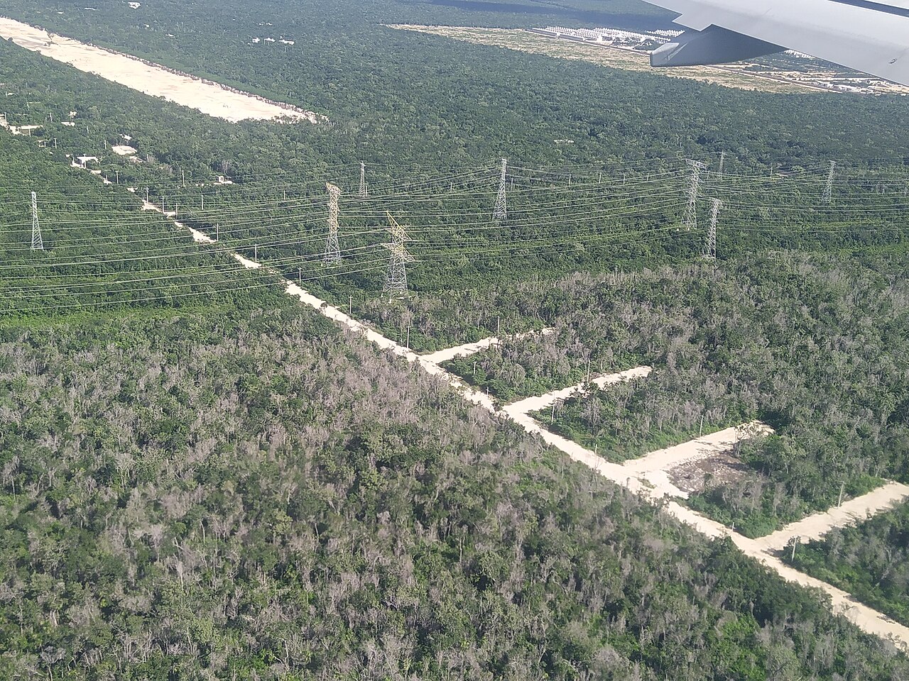
No grid delivers 100% of the energy it generates. This article gives realistic loss figures for transmission and distribution networks, explains the physics behind them, and sets out the engineering measures that actually reduce them.
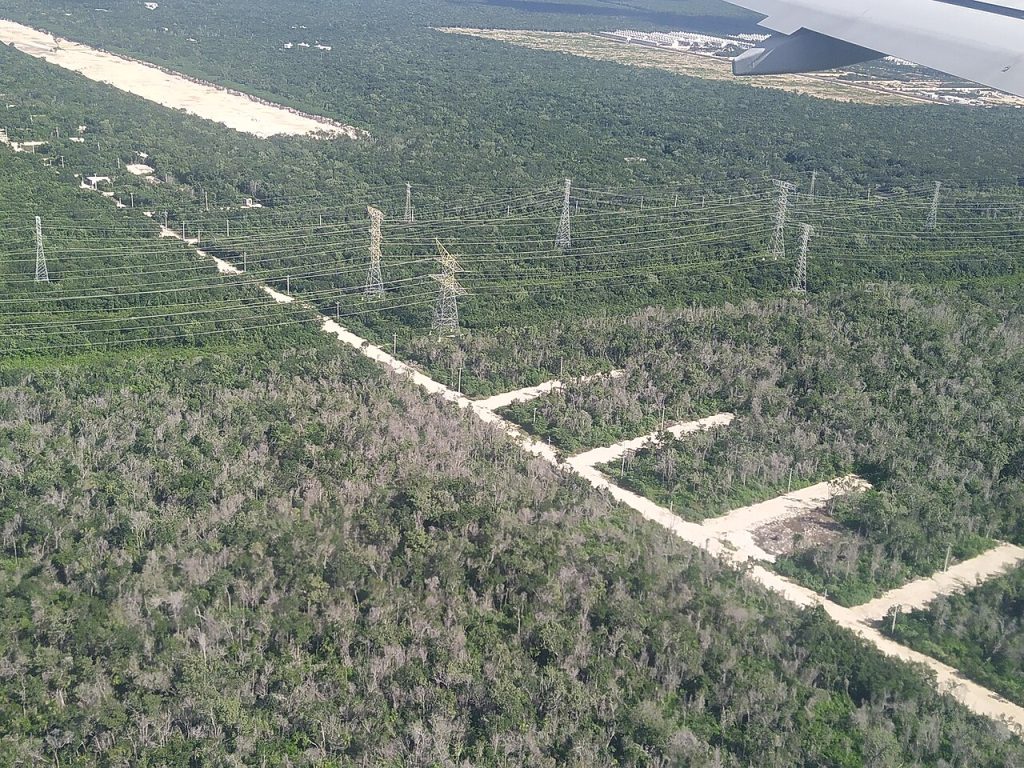
The Short Answer: Typical Loss Levels
Total transmission and distribution (T&D) losses are usually given as a share of the electricity fed into the network:
- Well-developed grids (most of Western Europe, North America, Japan, Korea): about 5-8%. The US, for example, has long reported annual T&D losses of about 5%.
- Global average: roughly 8%.
- Emerging and stressed networks: often 10-20%, and in some systems more. A large part of this is non-technical loss, such as theft, meter errors and unbilled consumption.
Of the technical losses, transmission usually accounts for only about 1-3% of energy, because it runs at high voltage. Most of the loss happens in medium- and low-voltage distribution, where currents are high and conductors are numerous.
Where the Energy Goes
1. Resistive (I²R) losses in conductors
Current flowing through a conductor with resistance R dissipates power as heat: Ploss = I²R per phase. Loss rises with the square of current, so halving the current cuts loss to a quarter. Resistance also rises with temperature, by about 0.4% per °C for aluminium. A heavily loaded, hot conductor therefore loses proportionally more. These are “load losses”, which change with demand.
2. Transformer losses
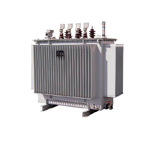
Every step-up and step-down transformer adds two kinds of loss:
- No-load (core) losses: hysteresis and eddy currents in the magnetic core. They are present 24/7 whenever the transformer is energized, even with no load.
- Load (copper) losses: I²R losses in the windings, which rise with loading.
Because a distribution network contains thousands of transformers, their no-load losses add up to a significant share of the total. Modern efficiency rules, such as the EU Ecodesign tiers and the efficiency classes in IEC 60076-20, limit both values.
3. Corona losses
At extra-high voltage, the electric field at the conductor surface can ionize the surrounding air. This produces a faint glow, a hiss, radio interference and power loss. Corona loss is small in fair weather but rises sharply in rain, fog, snow or at high altitude. Designers control it with bundled conductors, larger conductor diameters and smooth hardware with grading rings.
4. Dielectric and leakage losses
Underground cables lose some energy in their insulation, and long cables draw large charging currents. Leakage across polluted insulators is usually negligible in energy terms, but it can lead to flashovers.
5. Reactive power flow
Reactive power does no useful work, but it still drives current through lines and transformers. A load at 0.8 power factor draws 25% more current than the same load at unity power factor. That means roughly 56% more I²R loss in the feeder.
A Worked Example: Why Voltage Matters
Take 100 MW sent over 100 km of three-phase line with about 0.07 Ω/km per phase (total R ≈ 7 Ω), at unity power factor:
| Line voltage | Current per phase | I²R loss (3 phases) | Loss as % of power sent |
|---|---|---|---|
| 110 kV | ≈ 525 A | ≈ 5.8 MW | ≈ 5.8% |
| 220 kV | ≈ 262 A | ≈ 1.4 MW | ≈ 1.4% |
| 500 kV | ≈ 115 A | ≈ 0.3 MW | ≈ 0.3% |
Doubling the voltage halves the current and quarters the resistive loss. That is why bulk power moves at 220-765 kV AC or as HVDC, and why voltage is stepped down only close to the load. In practice, higher-voltage lines also use larger or bundled conductors, which lowers R further.
Proven Ways to Reduce Losses
Raise the voltage
Upgrading a corridor from 66 kV to 132 kV, or distribution feeders from 11 kV to 20-33 kV, cuts current-related losses sharply. It also frees capacity for new load and for renewable generation.
Correct the power factor locally
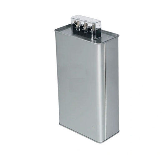
Shunt capacitor banks and active filters at substations and large consumer sites supply reactive power near where it is used. This lowers line current, improves voltage and releases transformer capacity. Explore our capacitors for power-factor correction.
Use low-loss transformers
Specify transformers with reduced no-load and load losses: high-grade grain-oriented steel or amorphous cores, optimized windings, and correct sizing. Lifetime loss evaluation (capitalizing losses in the tender) usually shows that a more efficient unit pays for itself. See our power transformers.
Use better conductors and network layout
- Re-conductor congested lines with larger or high-temperature low-sag (HTLS) conductors.
- Shorten LV feeders by placing distribution transformers closer to load centres.
- Balance load across the three phases. Unbalance increases neutral current and losses.
- Reconfigure open points and optimize voltage with automated switching and on-load tap changers.
Use HVDC for long distances and subsea links
For very long overhead routes and for submarine or underground cables, HVDC avoids reactive charging current and skin effect. Ultra-high-voltage DC links such as ±800 kV lose on the order of 3% per 1,000 km of line, plus converter station losses of below 1% per station. That is why HVDC carries remote hydro, wind and solar power to cities thousands of kilometres away.
Measure and digitalize
Smart meters, feeder monitoring and energy-balance analytics separate technical from non-technical losses and show utilities exactly where to invest. Distributed generation and storage near the load also reduce power flows over long distances.
Frequently Asked Questions
Is 5% transmission loss normal?
For combined transmission and distribution in a developed grid, yes. Losses on the high-voltage transmission system alone are typically lower, around 1-3%.
Why not transmit everything at the highest possible voltage?
Higher voltage means taller towers, longer insulator strings, wider rights-of-way, more corona and more expensive substations. The best voltage balances investment cost against the value of the energy lost.
Do underground cables lose less than overhead lines?
Cables often have lower resistive loss per km because of larger conductors. However, AC cables add dielectric losses and charging current, which limits long AC cable runs. That is a key reason subsea links use HVDC.
Does improving power factor reduce my electricity bill?
Often it does. Many tariffs penalize low power factor or charge for kVA demand, and correcting it also lowers losses inside your own installation.
Work with METTZ Group
METTZ Group offers a wide range of transformers and grid equipment to suit many needs, from low-loss distribution transformers to capacitor banks and fittings for high-voltage lines. Check out our website to learn more, or contact METTZ Group today to work with a representative.
