
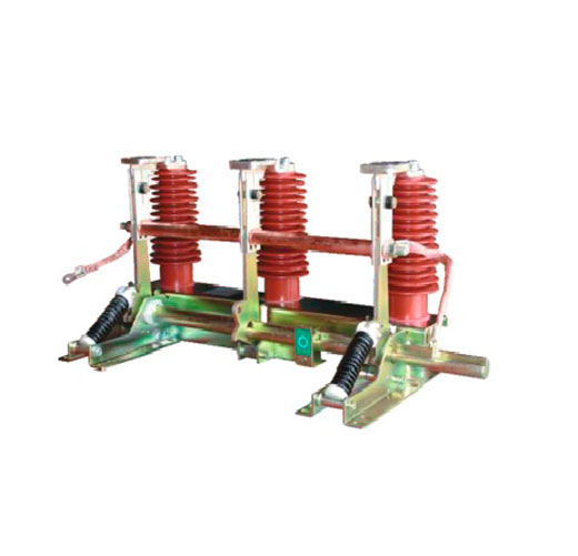
An earthing switch is the device that turns a “switched-off” circuit into a circuit that is safe to touch. This guide explains what an earthing switch actually does, where it sits in MV and HV installations, and how the IEC 62271-102 making-capacity classes E0, E1 and E2 should guide your specification.
Why “Off” Is Not the Same as “Safe”
Opening a circuit breaker or a disconnector stops the flow of current, but it does not make the conductors safe. An isolated cable or overhead line can still carry dangerous voltage from several sources:
- Trapped capacitive charge – a long MV cable behaves like a capacitor and can hold a lethal charge for a long time after it is switched off.
- Induced voltage – a de-energized line running parallel to a live one picks up voltage and current through electric and magnetic coupling.
- Backfeed – a generator, PV inverter, ring network or a wrongly closed switch at the remote end can re-energize the circuit.
An earthing switch deals with all of these by connecting the phase conductors solidly to the earthing system and to each other. Any residual charge drains away, induced currents flow harmlessly to earth, and if the circuit is accidentally re-energized, the result is a bolted short circuit that the upstream protection clears in milliseconds, instead of a live conductor in someone’s hands.
What an Earthing Switch Is – and What It Is Not
IEC 62271-102 defines an earthing switch as a mechanical switching device for earthing parts of a circuit, able to withstand short-circuit currents for a specified time, but not required to carry current in normal service. That last point matters: an earthing switch is not a protective device. It does not detect faults or open automatically. It is closed deliberately, by an operator or a remote command, once the circuit has been switched off and isolated.
Some marketing texts describe earthing switches as devices that “close when a fault occurs and divert fault current to ground”. That is not how they work. Fault clearing is the job of circuit breakers and fuses. The earthing switch only ever sees fault current in two situations: when it is closed onto a circuit that turns out to be live, and when an upstream fault occurs while it is closed. In both cases it must survive the current until the protection trips.
Earthing switch vs disconnector vs circuit breaker
| Device | Main job | Breaks load current? | Breaks fault current? | Typical standard |
|---|---|---|---|---|
| Circuit breaker | Switching and protection | Yes | Yes | IEC 62271-100 |
| Load break switch | Switching load currents | Yes | No (may make onto a fault) | IEC 62271-103 |
| Disconnector | Providing a safe isolating distance | No (negligible current only) | No | IEC 62271-102 |
| Earthing switch | Connecting isolated conductors to earth | No | No (rated to make and withstand it) | IEC 62271-102 |
In practice the disconnector and the earthing switch work as a pair: the disconnector (or the isolating gap of a switch) creates the gap, and the earthing switch earths the side where people will work. In ANSI markets the same device is usually called a grounding switch, and outdoor HV air switches are covered by IEEE C37.30.1.
Where You Find Earthing Switches
- Ring main units and compact MV switchgear – usually a three-position switch (closed, open, earthed) that combines the load break switch and earthing switch in one mechanism, so the two can never be closed at the same time.
- Air-insulated MV panels – a separate earthing switch in the cable compartment, mechanically interlocked with the withdrawable circuit breaker.
- Gas-insulated switchgear (GIS) – maintenance earthing switches and, on line and cable feeders, fast-acting (make-proof) earthing switches.
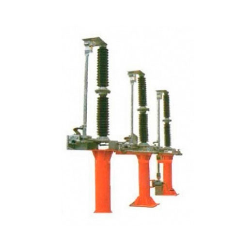
- Outdoor substations – earthing blades mounted on the base of the disconnector, or free-standing earthing switches on busbars.
- Transformer, capacitor bank and generator circuits – to discharge and earth equipment before maintenance.
How It Works
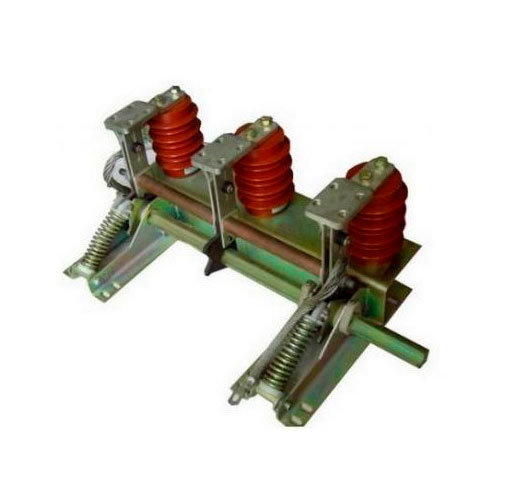
Mechanically, an earthing switch is a set of three moving contacts (blades or pins) driven by a common shaft. Each contact closes onto a fixed contact connected to a phase conductor, while the moving side is connected to the earthing busbar through flexible copper braids or sliding contacts.
A typical operating sequence looks like this:
- The circuit breaker or load break switch interrupts the current.
- The disconnector (or switch) opens to provide a visible or reliably indicated isolating gap.
- The operator confirms the absence of voltage, for example with the built-in voltage presence indicating system.
- The earthing switch is closed with a spring-assisted, independent mechanism, so closing speed does not depend on how fast the operator moves the handle.
- Work begins. After the work, the earthing switch is opened and the circuit is restored in reverse order.
The spring-assisted closing is not a detail. If the switch is closed onto a live circuit, a slow closing would let an arc burn across a shrinking gap. A snap-action mechanism makes the contact fast and firmly, which is what allows it to be rated for short-circuit making.
Making-Capacity Classes E0, E1 and E2
The most important rating to understand when you specify an earthing switch is its short-circuit making class under IEC 62271-102:
| Class | Short-circuit making capability | Typical use |
|---|---|---|
| E0 | None. Only rated to withstand short-circuit current once closed. | Locations where closing onto a live circuit is excluded by design and interlocks, such as some busbar or GIS maintenance earthing switches |
| E1 | Two making operations at rated short-circuit making current | Most HV applications and many MV panels |
| E2 | Five making operations, with reduced maintenance (applies up to 52 kV) | MV switchgear and RMUs where closing on a live cable is a realistic risk |
For distribution switchgear, E2 has become the default choice because cable networks are exactly where mistakes happen: a remote end left closed, a wrong cable identified, or backfeed from a customer generator. After such an event an E1 switch may need inspection and an E0 switch may be destroyed, while an E2 switch is designed to make the fault current several times and remain in service.
Other ratings to check
- Rated short-time withstand current (Ik) and duration (tk) – for example 20 kA for 3 s or 25 kA for 1 s. It must match the switchgear and the network fault level.
- Rated peak withstand current (Ip) – 2.5 × Ik at 50 Hz and 2.6 × Ik at 60 Hz under IEC.
- Rated voltage and insulation level – across the open earthing gap as well as to earth.
- Mechanical endurance class – the number of operations the mechanism is tested for.
- Induced current switching class A or B – for earthing switches at 52 kV and above on lines that run parallel to energized circuits. They must be able to make and break the induced capacitive and inductive currents.
Special Types: High-Speed and Fast-Acting Earthing Switches
Beyond the maintenance earthing switch, two specialized variants are worth knowing:
- High-speed earthing switches (HSES) are used on EHV transmission lines with single-pole auto-reclosing. After the breakers open one faulted phase, the HSES briefly earths that phase to extinguish the secondary arc fed by coupling from the healthy phases, then opens again before reclosing.
- Fast-acting or ultra-fast earthing devices are used in some MV and LV switchgear as active internal arc protection. When an arc is detected, the device creates a low-impedance three-phase short circuit within a few milliseconds, collapsing the arc voltage before the upstream breaker clears the fault.
Integrated or Stand-Alone?
In modern MV switchgear the earthing switch is almost always integrated and tested with the panel as part of the IEC 62271-200 type tests. Integration brings real benefits: mechanical interlocks are built in, the earthing path is short and type-tested at the full short-time current, and the position indicator is visible on the mimic diagram.
Stand-alone earthing switches remain common in outdoor AIS substations, on busbars and at line entries. Here the quality of the connection to the substation earthing grid is critical. A perfect switch is useless if it is bonded to the grid through a corroded or undersized conductor.
Specification Checklist
- Rated voltage, insulation level and frequency matching the switchgear
- Short-time withstand current and duration equal to or above the network fault level
- Making class E2 for MV cable circuits, unless interlocks fully exclude closing onto a live circuit
- Independent, spring-assisted operating mechanism, manual or motorized
- Reliable position indication and, where required, auxiliary contacts for SCADA
- Mechanical interlocks with the associated switch or breaker, plus padlocking facilities
- Suitability for the environment: indoor or outdoor, altitude, pollution class, tropical or mining duty
Interlocks and switching sequences are covered in our separate article on safe earthing switch operation.
Frequently Asked Questions
Is an earthing switch the same as a grounding switch?
Yes. “Earthing” is the IEC and British term, “grounding” the North American one. The function is identical.
Can an earthing switch interrupt current?
No. A standard earthing switch is not designed to break load or fault current. Only switches rated for induced current switching, mainly at 52 kV and above, can make and break the small induced currents from parallel lines.
Which making class should I choose for an RMU?
Class E2 is the usual choice for ring main units and MV cable feeders, because closing onto a cable that is still live from the remote end is a realistic risk in distribution networks.
Work with METTZ Group
METTZ Group offers a wide range of earthing switches to suit many needs – from indoor units for MV switchgear panels and ring main units to outdoor designs for substations, mining sites and tropical climates, alongside matching disconnectors and complete medium-voltage switchgear. Check out our website to learn more, or contact METTZ Group today to work with a representative.
